Doc. BIR-HW-09Rev. 2026.1
Hardware
Residency
A nine-week in-residence programme at TinkerSpace Kochi for people who build things that plug in, move, sense and ship.
Section 01 — Schedule
Nine weeks from first sketch to demo day.
Three phases, ten weeks, three checkpoints. Sundays are dedicated mentor catch-ups; Maker Thursdays are the weekly community checkpoint from week 03.
Phase A
Define
Arrive, find the idea, and defend an architecture you can actually build.
Weeks 00–02
Week 00
Arrive & connect
Understand the residency, meet the cohort, and begin shaping the project you will build.
Leave withA first project direction
Week 01
Define the idea
Learn the role of TinkerHub and TinkerSpace, share an early brief, gather mentor input, and finalise your idea.
Leave withIdea + architecture presentation
Week 02
Architecture review
Present to domain experts, get technical direction, and learn how to document a replicable project.
Checkpoint 01 · Idea & architecture
Leave withDocumented project plan
Phase B
Build
Get to a prototype, break it in public, and rebuild it with the room's help.
Weeks 03–05
Week 03
Start building
Present to new makers, learn practical electronics workflows, and work deeply enough to find the real problems.
Leave withBuild log + problem list
Week 04
Unblock the prototype
Bring a working fragment, surface pain points, and use the room to rethink, find collaborators, and solve them.
Leave withDemo-ready prototype
Week 05
Show the prototype
Demo to partners, supporters, and the maker community; share learnings and collect feedback for the next iteration.
Checkpoint 02 · Closed-room demo
Leave withHalfway prototype demo
Phase C
Ship
Move off the breadboard, give the build a body, and put it in front of people.
Weeks 06–09
Week 06
Finalise the build
Turn feedback into a final prototype with closed-room mentor support. Learn the basics of PCB design and fabrication.
Leave withFinalised prototype plan
Week 07
Make it physical
Present the final electronics design, move beyond the breadboard where appropriate, and learn casing and body design.
Leave withPCB/brownboard + enclosure
Week 08
Polish & prepare
Present the near-final project, resolve remaining issues, and prepare the story and video for demo day.
Leave withFinal presentation + video
Week 09
Demo & celebrate
Share the finished work publicly, meet partners and the community, and reflect on the growth of the cohort.
Checkpoint 03 · Demo day
Leave withPublic demo day
Section 02 — Mentors
The people in the room when it stops working.
Domain experts and makers who sit with residents through architecture reviews, checkpoints and the week everything breaks.

Salman Faris

Siddharth Shivkumar

Saheen Palayi
Devadath S

Kurian Jacob

Akash
Section 03 — Builders
This year’s residents.
17 builders, nine weeks, one documented hardware project each.

Adriel Jacob
Alen Thomas K
Amrutha M

Aswin
Jayasurya Jayakumar

Jinu Rose Mathew

Lakshmi S Madhav
Loyd Augustine
Mishal Shanavas

Nihaal Yoosuf

Nikhil S
Niveditaa Sunu

Riz Mariya Davis

S Agnivesh

Shamil Muneer

Vaishnav Prabhath

Vishakh V
Section 04 — Media
The people who documented it.
Photos, video and the story of the cohort, from Maker Thursdays through demo day.

Alina Pinheiro

Cyril Luke Anish
Section 05 — Learn in public
The build is yours. The learning belongs to the room.
Alongside your own project, every resident contributes four things back to the space.
01
Introduction to 3D printing
A working session on the machines in the space, so the enclosure is not the thing that stops you.
02
Attend a Tinkering With session
Sit in on someone else's build and learn how they debug it.
03
Host a Maker Thursday
Run the weekly community checkpoint once. Teach what you just learned.
04
Make a deep-dive video
Pick one component, take it apart, and explain it to everyone who comes next.
A strong portfolio project, practical circuit, firmware, CAD and documentation skills—and a lasting habit of contributing to maker communities.
Section 06 — Project index
Every hardware build.
The README included.
01CuBaffle
Step 2: Install Dependencies Install the required Python packages for the web dashboard and camera stream: First-time setup:
CuBaffle
Step 2: Install Dependencies Install the required Python packages for the web dashboard and camera stream: First-time setup:
Project documentation
Weekly log Open repositoryCubaffle - Deployable Optical Baffle Demonstrator
This repository contains the complete documentation, CAD files, and control software to build a ground-based functional prototype of a deployable optical baffle for a 1U CubeSat. The project aims to solve the volume vs. accuracy contradiction in high-accuracy star trackers by utilizing a 3-stage telescoping baffle that stows completely within a 1U chassis (10x10x10 cm) and deploys to 8 cm using a dual-servo Scotch Yoke mechanism.
Repository Structure
docs/— roject overview, mathematical kinematic models, and weekly sprint logs documenting the engineering process, trade studies, and troubleshooting.code/— Python firmware and scripts to run the hardware PWM, command-line interface, and the web-based visual analysis dashboard.cad/— 3D models (.step, .kcl, .stl) for the 3-stage telescoping baffle and servo mechanisms, plus the 2D vector file (.svg) for the laser-cut acrylic CubeSat chassis.
Hardware Bill of Materials (BOM)
- Compute & Optics: Raspberry Pi 5, Raspberry Pi Camera Module 3.
- Actuation: 2x MG90S Micro Servos.
- Power: 4x AA Battery Holder (supplying a dedicated 6V to servos), standard RPi 5 power supply.
- Chassis: 2.88mm transparent acrylic sheet (for laser cutting).
- Baffle: 3D Printer filament (Matte Black recommended for optical testing; PLA/PETG acceptable).
- Misc: Perf board, jumper wires, M2.5/M3 screws, super glue, liquid dish soap (for plastic lubrication).
Fabrication & Assembly
- Laser Cut the Chassis: Use the provided .svg file in the cad/ directory to laser cut the 1U CubeSat body out of 2.88mm acrylic. The standard CubeSat rails have been omitted to simplify ground testing.
- 3D Print the Baffle: Print the base plate, middle segment, and top plate.
- Crucial Assembly Note: Due to the overlapping retaining lips (0.40mm clearance), the lower baffle segment cannot be printed directly onto the base plate if you want to assemble the middle stage over it. Print the lower baffle segment as a separate piece, slide the middle segment over it, and then super-glue the lower segment to the base plate.
- Mechanism Setup: Mount the MG90S servos into the base plate pockets. Attach the custom 7.5cm / 8.0cm servo arms.
- Lubrication: Sand the layer lines of the 3D-printed cylinders smooth and apply a single drop of liquid dish soap to the sliding surfaces to prevent binding. Do not use Vaseline.
Electronics & Wiring
To prevent torque spikes from browning out or damaging the Raspberry Pi, the servos must be powered by a completely isolated 6V power supply (the 4x AA pack) with a shared common ground.
Software Setup
The control software utilizes the Raspberry Pi's hardware PWM blocks to ensure jitter-free servo motion.
Step 1: Enable Hardware PWM
Open your /boot/firmware/config.txt and append the following line to enable the 2-channel PWM overlay:
dtoverlay=pwm-2chan,pin=12,func=4,pin2=13,func2=4
Reboot the Raspberry Pi after saving.
Step 2: Install Dependencies Install the required Python packages for the web dashboard and camera stream: First-time setup:
sudo apt update sudo apt install python3-flask python3-opencv python3-picamera2
02MARS Modular Autonomous Rover System
Open-source autonomous rover with one reusable base and swappable task modules. ESP32-S3 powered, with ultrasonic obstacle avoidance and live camera streaming. Currently supports Disaster Search (gas/smoke/temp sensing) and Delivery (QR-verified unlock) modules — built for future expansion without redesigning the base.
MARS Modular Autonomous Rover System
Open-source autonomous rover with one reusable base and swappable task modules. ESP32-S3 powered, with ultrasonic obstacle avoidance and live camera streaming. Currently supports Disaster Search (gas/smoke/temp sensing) and Delivery (QR-verified unlock) modules — built for future expansion without redesigning the base.
Project documentation
Weekly log Open repositoryMARS — Modular Autonomous Rover System 🤖
One rover. Multiple capabilities.
MARS (Modular Autonomous Rover System) is a modular robotic platform developed to explore how a single autonomous rover can be adapted for different real-world applications through interchangeable modules.
The project started with a simple question:
Instead of building a different robot for every task, can one rover be designed to perform multiple tasks by changing its module?
This idea led to the development of a common rover base with autonomous movement, obstacle detection, wireless control, and interchangeable application-specific modules.
🚀 Project Overview
MARS consists of two main parts:
                 ┌──────────────────────┐
                 │      MARS BASE       │
                 │      ROVER           │
                 │                      │
                 │ • Autonomous Motion  │
                 │ • Obstacle Detection │
                 │ • Wireless Control   │
                 │ • Modular Interface  │
                 └──────────┬───────────┘
                            │
             ┌──────────────┴──────────────┐
             │                             │
             ▼                             ▼
   ┌───────────────────┐       ┌────────────────────┐
   │ Raspberry Pi      │       │ Environmental      │
   │ Camera Module     │       │ Monitoring Module  │
   │                   │       │                    │
   │ • Webcam          │       │ • Gas Sensor       │
   │ • Live Streaming  │       │ • Soil Moisture    │
   │                   │       │ • Temperature      │
   └───────────────────┘       │ • Humidity         │
                               │ • Servo Mechanism  │
                               └────────────────────┘
The base rover provides mobility and autonomous navigation, while application-specific modules extend its functionality.
🎯 Objectives
The main objectives of MARS are:
- Develop a functional autonomous rover platform.
- Implement obstacle detection and avoidance.
- Enable wireless control of the rover.
- Develop a modular mechanism for attaching different application modules.
- Explore Raspberry Pi-based vision and remote monitoring.
- Develop an environmental sensing module.
- Integrate mechanical, electronic, and software systems into a single platform.
- Create a flexible platform that can be adapted for different field applications.
🛠️ Hardware
Base Rover
| Component | Purpose |
|---|---|
| Arduino Uno | Main controller |
| DC Geared Motors | Rover movement |
| Motor Driver | Motor control |
| 14.8 V Battery | Main power source |
| Buck Converter | Voltage regulation |
| Ultrasonic Sensors | Obstacle detection |
| Bluetooth Module | Wireless control |
| 65 mm Universal Hub Tyres | Rover movement |
| Perfboard | Permanent circuit |
| 3D-Printed Chassis | Mechanical structure |
Camera Module
| Component | Purpose |
|---|---|
| Raspberry Pi | Processing and streaming |
| Webcam | Live video capture |
Environmental Monitoring Module
| Component | Purpose |
|---|---|
| Arduino Nano | Module controller |
| Gas Sensor | Gas detection |
| Soil Moisture Sensor | Soil moisture measurement |
| Temperature & Humidity Sensor | Environmental monitoring |
| Servo Motor | Raises/lowers the soil moisture sensor |
⚙️ Base Rover
The base rover went through several stages of development.
1. Initial Prototype
The first prototype was built using a temporary foam-board base. This allowed the basic components and movement system to be tested before developing the final mechanical structure.
2. Controller and Communication
The project initially used an ESP32-S3 because of its built-in Wi-Fi capability.
During testing, the ESP32-S3 was damaged following a short circuit. We then adapted the rover to an Arduino Uno.
Since the Arduino Uno does not have built-in Wi-Fi, the communication system was changed from Wi-Fi-based control to Bluetooth control.
Bluetooth Serial Terminal
            ↓
      Bluetooth Module
            ↓
        Arduino Uno
            ↓
       Motor Driver
            ↓
          Motors
3. Obstacle Detection
Three ultrasonic sensors were used at the front of the rover.
The sensors were arranged approximately as:
             Front
               ↑

       \       |       /
        \      |      /
       +25°   0°   -25°

       Ultrasonic Sensors
This arrangement was tested to improve obstacle detection coverage in the direction of movement.
4. Autonomous Movement
The rover was developed to:
- Move forward
- Move backward
- Turn left
- Turn right
- Stop when an obstacle is detected
- Continue movement after the obstacle is removed
We also experimented with point-to-point movement using a predefined room map, testing movements such as A → B.
🔧 Mechanical Development
The mechanical structure evolved throughout the project.
The initial prototype used a 30 × 30 cm foam-board base. Later, a more compact 3D-printed structure was developed with approximate dimensions of 21 × 18 cm.
The CAD structure included provisions for:
- Battery mounting
- Ultrasonic sensor mounting
- Electronic component placement
- Module integration
The design was developed using Zoo Keeper and Fusion 360, followed by 3D printing and physical testing.
🔌 Electrical Development
The rover initially used a breadboard for temporary connections.
As the design became more stable, the circuit was transferred to a perfboard.
Breadboard Prototype
        ↓
Component Testing
        ↓
Circuit Verification
        ↓
Perfboard
        ↓
Soldering & Wiring
        ↓
3D-Printed Integration
The permanent circuit contains the main control, communication, sensing, motor-control, and power-regulation components.
🧩 Application Modules
The modular architecture is the main concept behind MARS.
Instead of modifying the entire rover for every application, different modules can be attached to the same base platform.
📷 1. Raspberry Pi Camera Module
A Raspberry Pi and webcam were integrated as a separate module to provide live video streaming.
The development involved learning the Raspberry Pi setup process, including:
- Operating system installation
- Initial configuration
- Connecting the Raspberry Pi
- Connecting the webcam
- Network configuration
- Live video streaming
System Flow
       Webcam
          ↓
    Raspberry Pi
          ↓
      Wi-Fi Network
          ↓
    Live Video Stream
          ↓
     Remote User
This module can be used for applications such as:
- Remote inspection
- Surveillance
- Visual monitoring
- Disaster-area observation
🌱 2. Environmental Monitoring Module
The second module was developed using an Arduino Nano.
It combines multiple sensors to collect environmental information.
Sensors
- Gas sensor
- Soil moisture sensor
- Temperature sensor
- Humidity sensor
A servo motor was also incorporated to mechanically raise and lower the soil-moisture sensor when required.
Gas Sensor ─────────────┐
                        │
Soil Moisture Sensor ───┤
                        │
Temperature/Humidity ───┤
                        ↓
                    Arduino Nano
                        │
                        ↓
                   Sensor Data

                  Servo Motor
                       ↓
          Raise / Lower Moisture Sensor
This module demonstrates how MARS can be adapted for environmental monitoring applications.
📅 Development Timeline
| Week | Major Development |
|---|---|
| Week 0 | MARS concept, system architecture and component planning |
| Week 1 | Initial rover prototype and component procurement |
| Week 2 | Component testing, 3D-printing and PCB design learning |
| Week 3 | ESP32-S3 integration, Wi-Fi control and obstacle detection |
| Week 4 | Autonomous movement experiments and sensor arrangement |
| Week 5 | ESP32-S3 failure, Arduino Uno adaptation and Bluetooth control |
| Week 6 | Ultrasonic integration, point-to-point navigation and CAD development |
| Week 7 | New tyres, perfboard conversion and 3D-printed integration |
| Week 8 | Permanent electrical system and room-based sensor testing |
| Week 9 | Raspberry Pi camera module and environmental monitoring module |
🧠 Key Learning
The development of MARS involved learning across multiple areas:
Electronics
- Motor drivers
- DC motor control
- Ultrasonic sensing
- Voltage regulation
- Battery-powered systems
- Perfboard soldering
- Sensor integration
Embedded Systems
- Arduino Uno
- Arduino Nano
- ESP32-S3
- Bluetooth communication
- Wi-Fi communication
- Sensor interfacing
Raspberry Pi
- OS installation
- Initial configuration
- Peripheral connections
- Webcam integration
- Network configuration
- Live video streaming
Mechanical Design
- CAD modelling
- 3D printing
- Mechanical tolerances
- Component mounting
- Chassis design
- Module integration
Robotics
- Obstacle detection
- Autonomous movement
- Point-to-point navigation
- Environmental sensing
- Modular robotic architecture
📂 Repository Structure
MARS-Modular-Autonomous-Rover-System/
│
├── README.md
│
├── docs/
│   ├── week-00.md
│   ├── week-01.md
│   ├── week-02.md
│   ├── week-03.md
│   ├── week-04.md
│   ├── week-05.md
│   ├── week-06.md
│   ├── week-07.md
│   ├── week-08.md
│   └── week-09.md
│
├── code/
│   ├── base-rover/
│   ├── obstacle-avoidance/
│   ├── bluetooth-control/
│   ├── raspberry-pi-camera/
│   └── environmental-module/
│
├── cad/
│   ├── rover-base/
│   └── modules/
│
├── images/
│   ├── base-rover/
│   ├── camera-module/
│   └── environmental-module/
│
└── circuit/
    └── perfboard/
🔮 Future Improvements
Possible future developments for MARS include:
- Improved autonomous navigation
- More accurate mapping
- GPS-based outdoor navigation
- Better obstacle avoidance algorithms
- Wireless sensor-data transmission
- Additional application modules
- Improved modular attachment mechanism
- Battery monitoring
- Remote monitoring dashboard
- Integration of computer vision
- Autonomous task-based module selection
👥 Project
MARS — Modular Autonomous Rover System
Developed as a collaborative engineering project with a focus on robotics, embedded systems, IoT, mechanical design, and modular architecture.
The project documentation records the development process, challenges, design decisions, testing, and learning throughout the build.
MARS is not just a rover. It is a platform designed to become different robots for different tasks.
03InfiniteInferno
A modular computer-vision and autonomous-drone development project combining real-time person detection, tracking, gesture intent recognition, bounded follow-control logic, Raspberry Pi/UNO Q experimentation, Pixhawk flight control, and a custom drone frame.
InfiniteInferno
A modular computer-vision and autonomous-drone development project combining real-time person detection, tracking, gesture intent recognition, bounded follow-control logic, Raspberry Pi/UNO Q experimentation, Pixhawk flight control, and a custom drone frame.
Project documentation
Weekly log Open repositoryARGUS — Autonomous Vision-Based Drone
A modular computer-vision and autonomous-drone development project combining real-time person detection, tracking, gesture intent recognition, bounded follow-control logic, Raspberry Pi/UNO Q experimentation, Pixhawk flight control, and a custom drone frame.






Table of Contents
- Overview
- Project Objective
- System Architecture
- Current Software Implementation
- Computer Vision Pipeline
- Person Detection
- Tracking
- Gesture Recognition
- Follow Controller
- Safety-Oriented Control Logic
- Camera System
- Model and Inference
- Configuration
- Hardware Development
- Flight Controller Integration
- Development Timeline
- Repository Structure
- Requirements
- Installation
- Running the Vision Pipeline
- Raspberry Pi Smoke Test
- Testing
- Example Output
- Project Images
- Technical Design Notes
- Limitations and Current Status
- Future Development
- License
Overview
ARGUS is an autonomous-drone development project centered around onboard computer vision and target-following behavior.
The project was developed as a modular system so that the perception, tracking, gesture interpretation, and flight-control layers can be developed and tested independently.
The documented project progression includes:
- Initial feasibility study for autonomous person/object tracking.
- Raspberry Pi camera and computer-vision setup.
- Real-time person detection and tracking.
- Model refinement and Raspberry Pi implementation.
- Custom 3D drone-component design and physical testing.
- Evaluation of Raspberry Pi and Arduino UNO Q as companion-computing platforms.
- UNO Q implementation and computer-vision integration.
- Hardware assembly and power-system repair.
- Pixhawk/PX4 calibration, ESC troubleshooting, and first-flight testing.
The repository contains both the project-development documentation and the Python vision/control prototype.
Project Objective
The core technical objective is to build a drone system capable of:
- Detecting people in the camera view.
- Assigning session-local tracking IDs.
- Maintaining a selected target across frames.
- Interpreting simple hand gestures from pose keypoints.
- Converting target geometry into bounded movement intents.
- Providing a safe interface between computer vision and a future autopilot-control layer.
- Integrating the companion-computing system with a Pixhawk-based drone.
- Supporting future autonomous pursuit and gesture-triggered actions.
The system is deliberately modular: computer vision does not directly drive motors in the current Python implementation.
System Architecture
                         ┌───────────────────────┐
                         │   Camera / Video      │
                         │  Raspberry Pi Camera  │
                         └───────────┬───────────┘
                                     │ RGB frame
                                     ▼
                         ┌───────────────────────┐
                         │     Preprocessing     │
                         │  Resize + Letterbox   │
                         │  Normalize + CHW      │
                         └───────────┬───────────┘
                                     │
                                     ▼
                         ┌───────────────────────┐
                         │   YOLOv8n / ONNX      │
                         │    CPU Inference      │
                         └───────────┬───────────┘
                                     │
                                     ▼
                         ┌───────────────────────┐
                         │     Postprocessing    │
                         │ Person filtering      │
                         │ Box decoding + NMS    │
                         │ Optional keypoints    │
                         └───────────┬───────────┘
                                     │
                                     ▼
                         ┌───────────────────────┐
                         │    Person Tracker     │
                         │ IoU + centroid match  │
                         │ Session-local IDs     │
                         └───────────┬───────────┘
                                     │
                    ┌────────────────┴────────────────┐
                    │                                 │
                    ▼                                 ▼
          ┌───────────────────┐             ┌───────────────────┐
          │ Gesture Recognizer│             │ Follow Controller │
          │ 17-point COCO     │             │ Target geometry   │
          │ pose keypoints    │             │ → bounded intent  │
          └─────────┬─────────┘             └─────────┬─────────┘
                    │                                 │
                    └────────────────┬────────────────┘
                                     ▼
                         ┌───────────────────────┐
                         │    Flight Intent      │
                         │ yaw / forward /       │
                         │ vertical / action     │
                         └───────────┬───────────┘
                                     │
                                     ▼
                         ┌───────────────────────┐
                         │ Future Autopilot      │
                         │ / MAVLink Interface   │
                         │ (not motor control in │
                         │ current Python code)  │
                         └───────────────────────┘
Current Software Implementation
The checked-in Python package is named agni-vision and is described as a Raspberry Pi person-tracking and gesture-intent pipeline.
The software is organized into independent modules:
| Module | Responsibility |
|---|---|
camera.py | Camera abstraction for Picamera2/OpenCV |
preprocess.py | YOLO letterbox preprocessing |
detector.py | ONNX Runtime inference |
postprocess.py | Detection decoding, person filtering, NMS, pose keypoints |
tracker.py | Lightweight person tracking and session IDs |
gestures.py | Debounced hand-gesture recognition |
controller.py | Target-following and bounded flight-intent generation |
config.py | Typed YAML configuration and validation |
main.py | End-to-end command-line vision loop |
This separation allows individual components to be tested without requiring the complete drone hardware.
Computer Vision Pipeline
The current pipeline follows this sequence:
Camera Frame
    │
    ▼
RGB Image
    │
    ▼
Letterbox Resize
    │
    ▼
Normalized NCHW Tensor
    │
    ▼
YOLOv8n ONNX
    │
    ▼
Raw Detection Output
    │
    ▼
Person Class Filtering
    │
    ▼
Confidence Filtering
    │
    ▼
Non-Maximum Suppression
    │
    ▼
Person Detections
    │
    ▼
Lightweight Tracker
    │
    ▼
Track IDs
    │
    ├──────────────► Gesture Recognition
    │
    └──────────────► Follow Controller
                              │
                              ▼
                         Flight Intent
Person Detection
The repository includes:
code/models/yolov8n.onnx
code/models/yolov8n.pt
The ONNX model is loaded through ONNX Runtime using the CPU execution provider.
The detector:
- Loads the ONNX model.
- Reads its input shape dynamically.
- Configures ONNX Runtime thread settings.
- Enables graph optimization.
- Receives a normalized image tensor.
- Runs inference.
- Returns the raw model output.
The post-processing layer then identifies the person class and converts the model's bounding-box representation into image coordinates.
Preprocessing
The preprocessing module implements YOLO-style letterboxing.
For a camera frame:
Original frame
     │
     ▼
Maintain aspect ratio
     │
     ▼
Resize to fit model input
     │
     ▼
Pad remaining area
     │
     ▼
Normalize 0–255 → 0–1
     │
     ▼
HWC → CHW
     │
     ▼
Add batch dimension
The current configuration uses a camera resolution of:
640 × 480
and the bundled YOLOv8n model is expected to operate at:
640 × 640
The preprocessing code also stores the scale and padding values so detections can later be mapped back to the original camera coordinates.
Postprocessing
The post-processing stage supports two related output layouts:
Detection output
YOLO detection output is interpreted as:
x
y
width
height
class scores...
Only the person class is retained.
Pose output
The code also supports a 56-value pose row:
4 bounding-box values
+ 1 person confidence
+ 17 × (x, y, confidence)
This provides the keypoint data required by the gesture-recognition module.
Non-Maximum Suppression
Overlapping person detections are filtered using IoU-based NMS.
The configured threshold is:
iou_threshold: 0.45
Person Tracking
The tracker is intentionally lightweight and does not depend on a large external tracking framework.
Each detected person receives a session-local ID:
Person → Track ID
For example:
Person A → ID 1
Person B → ID 2
Person C → ID 3
The tracker associates detections with existing tracks using:
- Bounding-box IoU.
- Normalized center-point distance.
- Detection-to-track matching.
- Missed-frame tolerance.
Important parameters:
tracking:
  max_missed: 12
  min_hits: 2
  iou_threshold: 0.20
  max_center_distance: 0.18
A track becomes confirmed after the configured minimum number of successful hits.
A track can temporarily disappear and remain alive for a limited number of missed frames.
This is particularly useful when the target is briefly occluded.
Gesture Recognition
The gesture module uses 17-point COCO pose keypoints.
The implementation primarily uses:
Nose
Left Shoulder
Right Shoulder
Left Wrist
Right Wrist
The basic gesture logic compares wrist positions with shoulder positions.
Supported gestures:
| Gesture | Intent |
|---|---|
| Right hand up | start_follow |
| Left hand up | stop_follow |
| Both hands up | land |
The recognizer includes:
- Keypoint confidence threshold.
- Hold-frame requirement.
- Per-track gesture state.
- Gesture cooldown.
- Track-specific gesture events.
This prevents a gesture from triggering immediately because of a single noisy frame.
Current configuration:
gestures:
  hold_frames: 4
  cooldown_seconds: 2.0
  keypoint_threshold: 0.35
Follow Controller
The follow controller converts target geometry into bounded movement intents.
It does not directly control motors.
The generated intent contains:
{
  "yaw": 0.0,
  "forward": 0.0,
  "vertical": 0.0,
  "action": "follow",
  "target_id": 1,
  "reason": "target locked"
}
The controller considers:
Horizontal error
Target center ───────────────► Frame center
             horizontal error
Horizontal error is converted into a bounded yaw command.
Vertical error
The target's vertical position is compared with the frame center and converted into a bounded vertical intent.
Apparent target size
The target bounding-box area is compared with a desired area ratio.
This provides a simple distance proxy:
Target too small  → move forward
Target near target size → hold
Target too large → reduce forward motion
Current controller limits:
controller:
  target_area_ratio: 0.18
  deadband_x: 0.08
  deadband_y: 0.10
  max_yaw: 0.35
  max_forward: 0.30
  max_vertical: 0.25
  target_timeout_seconds: 0.75
Safety-Oriented Control Logic
The controller intentionally uses conservative behavior.
No target selected
follow = false
        ↓
hover intent
Target temporarily missing
The system does not immediately change the selected target.
Target lost
If the target remains unavailable beyond the timeout:
Target lost
    ↓
Safe hover intent
Gesture target locking
Once a target is selected, gestures from another tracked person cannot silently take over the control session.
Landing
The both_hands_up gesture can produce:
action = "land"
when it belongs to the currently permitted target.
Important
The current software outputs high-level flight intent JSON. It does not directly send PWM, motor commands, or MAVLink flight commands.
That separation is intentional and leaves the autopilot interface as a separate integration layer.
Camera System
The camera abstraction supports two backends.
Picamera2
Default Raspberry Pi backend:
camera:
  backend: picamera2
This is intended for Raspberry Pi camera hardware.
OpenCV
An OpenCV camera or video file can also be used:
camera:
  backend: opencv
The implementation converts OpenCV's BGR frames to RGB before passing them into the model pipeline.
This makes local development and video-file testing possible without requiring the Raspberry Pi camera stack.
Model and Inference
YOLOv8n
The repository includes:
models/yolov8n.onnx
models/yolov8n.pt
The ONNX version is used by the current runtime pipeline.
The detector uses:
ONNX Runtime
CPUExecutionProvider
with configurable intra-operation threading.
Current model settings:
model:
  path: models/yolov8n.onnx
  confidence: 0.45
  iou_threshold: 0.45
  threads: 4
  inference_stride: 2
Inference stride
With:
inference_stride: 2
the application performs model inference on every second frame.
This reduces computational load and can be useful on resource-constrained edge hardware.
Configuration
All major runtime parameters are centralized in:
code/configs/config.yaml
Configuration categories:
model
├── model path
├── confidence threshold
├── IoU threshold
├── CPU threads
└── inference stride

camera
├── backend
├── source
├── width
└── height

tracking
├── missed-frame tolerance
├── confirmation hits
├── IoU threshold
└── center-distance threshold

gestures
├── hold frames
├── cooldown
├── keypoint confidence
└── gesture → action mapping

controller
├── target area
├── horizontal deadband
├── vertical deadband
├── yaw limit
├── forward limit
├── vertical limit
└── target timeout
The Python configuration layer uses dataclasses and validates important safety-related values before the application starts.
Hardware Development
The physical drone development progressed alongside the software system.
Main hardware elements documented during development
- Raspberry Pi computer-vision platform.
- Raspberry Pi camera.
- Arduino UNO Q experimentation and integration.
- Pixhawk flight controller.
- ESCs and motors.
- Power Distribution Board (PDB).
- Drone frame and 3D-printed components.
- 3D-printed structural prototypes.
- Suitable drone power and mounting hardware.
3D Design and Manufacturing
The project included custom 3D design and physical prototyping.
The development process included:
Drone structural requirements
          ↓
3D component design
          ↓
Prototype printing
          ↓
Strength evaluation
          ↓
Design refinement
          ↓
Frame/component integration
A drone leg was initially printed as a prototype for strength and structural testing.
The project also encountered material constraints:
- PLA became temporarily unavailable during one stage.
- An alternative filament caused printing problems.
- Carbon-fibre-infused PETG was later considered for higher-strength components.
- Suitable screws and fasteners also affected the planned frame assembly.
To keep development moving, an already-available strong frame was used.
Flight Controller Integration
The documented flight-control development used a Pixhawk.
The project experimented with:
- QGroundControl.
- PX4 firmware.
- ArduPilot firmware.
- Mission Planner.
PX4 / QGroundControl
The successful configuration path used:
Pixhawk
   ↓
QGroundControl
   ↓
PX4 firmware
   ↓
Calibration
   ↓
ESC/motor connection verification
   ↓
Flight preparation
ESC troubleshooting
Incorrect ESC connections were identified during setup and corrected before flight testing.
ArduPilot / Mission Planner
ArduPilot firmware and Mission Planner were also tested, but the documented calibration attempt did not succeed.
The project then returned to:
PX4 + QGroundControl
for further configuration and calibration.
Development Timeline
Week 0 — Ideation and Feasibility
The project concept was established around:
- Person/object detection.
- Target tracking.
- Autonomous pursuit.
- Gesture-based actions.
- Pixhawk-based flight control.
The initial feasibility study compared Raspberry Pi and Arduino UNO Q in terms of compute capability, power, camera support, real-time behavior, and software ecosystem.
The project also established an initial safety constraint: autonomous flight experiments should begin in a tethered or controlled environment.
Week 1 — Computer Vision Setup
The Raspberry Pi vision environment was established.
Work included:
- Camera configuration.
- Live video acquisition.
- Computer-vision dependencies.
- Initial person detection.
- Tracking IDs.
- FPS/frame monitoring.
- Groundwork for hand-gesture recognition.
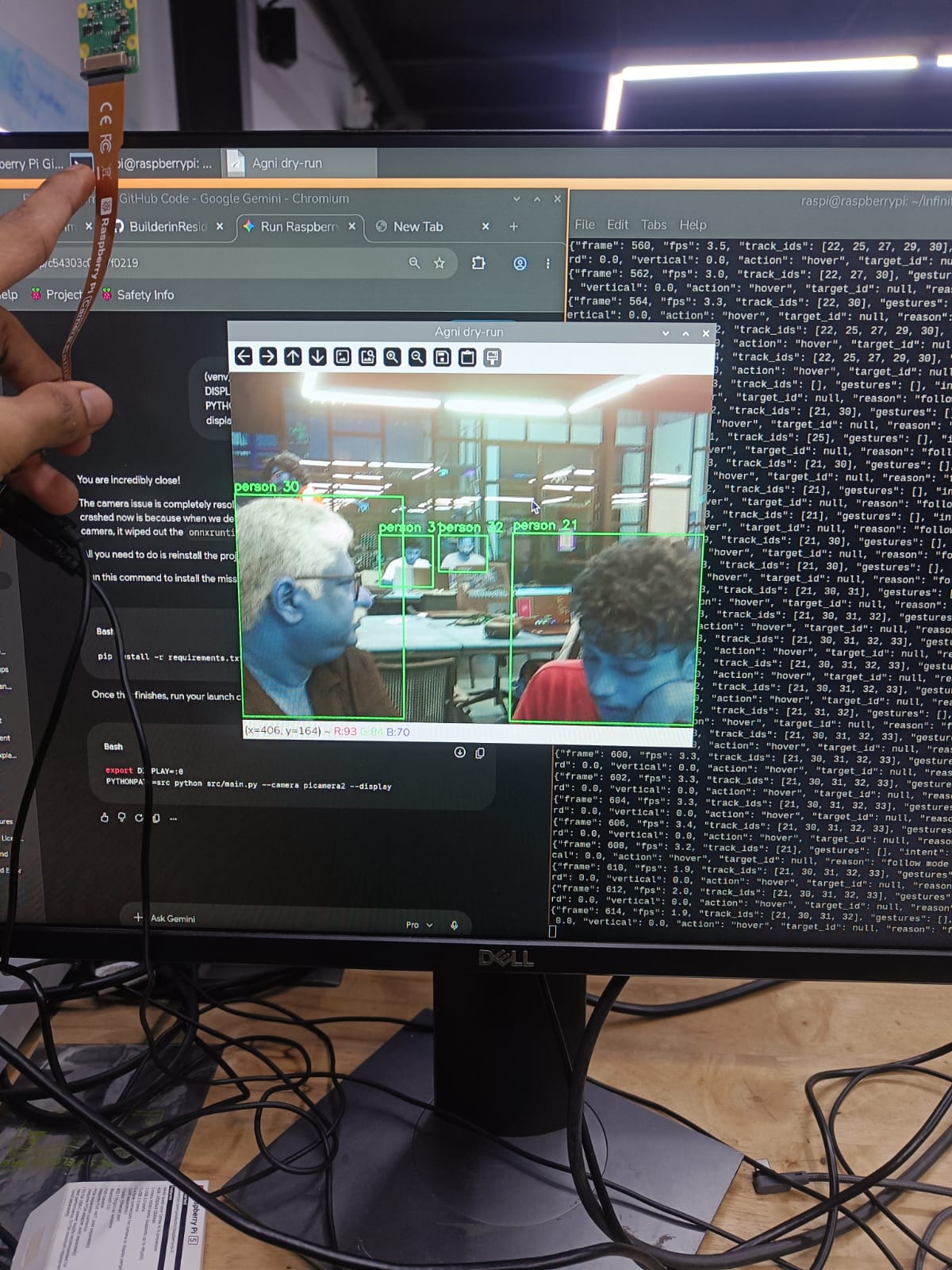
Initial camera testing demonstrated multiple detected people with bounding boxes and tracking IDs.
Week 2 — Model Refinement and 3D Design
The computer-vision model was deployed and refined on the Raspberry Pi.
Parallel mechanical development began with:
- Drone component design.
- Dimension planning.
- Mounting considerations.
- Assembly compatibility.
- Preparation for 3D printing.
Week 3 — Raspberry Pi Implementation and Prototype Testing
The Raspberry Pi implementation was completed for the computer-vision system.
Mechanical development progressed toward physical testing.
A 3D-printed drone leg was produced as an initial structural prototype for strength evaluation.
Week 4 — 3D Refinement and Drone Physics
The overall 3D-printed drone design was refined.
The development also considered:
- Thrust.
- Lift.
- Weight.
- Forces acting on the drone.
- Structural requirements.
A filament-availability problem caused printing delays and required printer cleaning before manufacturing could continue.
Week 5 — Project Continuity and Development Handoff
The project documentation records a transition in project participation and a technical briefing covering:
- Previous software work.
- 3D design.
- Printing.
- Drone physics.
- Current project state.
- Remaining development.
No teammate-specific information is included in this README.
Week 6 — Frame Selection and UNO Q
Mechanical work focused on frame material and hardware availability.
The planned carbon-fibre-infused PETG approach was affected by material availability, while PLA did not provide the required guaranteed strength for the intended application.
A strong available frame was therefore selected.
In parallel, work began on the Arduino UNO Q implementation.
Week 7 — UNO Q Debugging and Computer Vision
The Arduino UNO Q initially required troubleshooting and reset procedures.
The Raspberry Pi vision code was adapted toward UNO Q compatibility with AI-assisted code conversion and subsequent corrections.
The documented development then reached a stage where computer vision was implemented on the UNO Q.
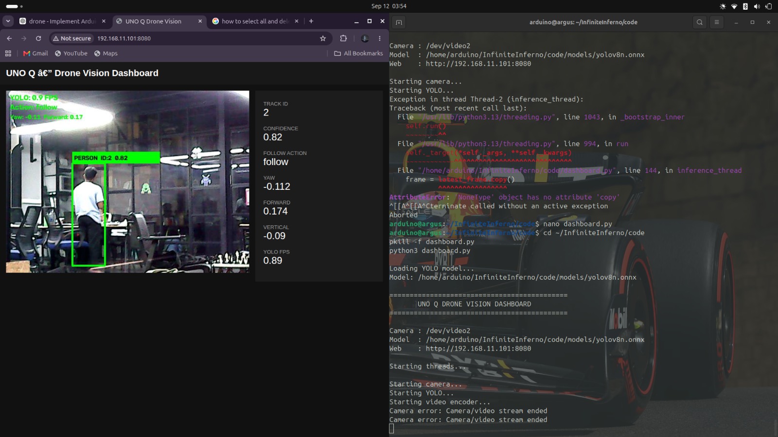
Week 8 — Hardware Assembly and PDB Replacement
The UNO Q was integrated into the drone hardware.
Major electronic components were positioned and soldered.
During power-up testing, the PDB failed.
The documented cause was the absence of a required capacitor. The PDB was replaced, a suitable capacitor was added, and the power-system connections were completed.
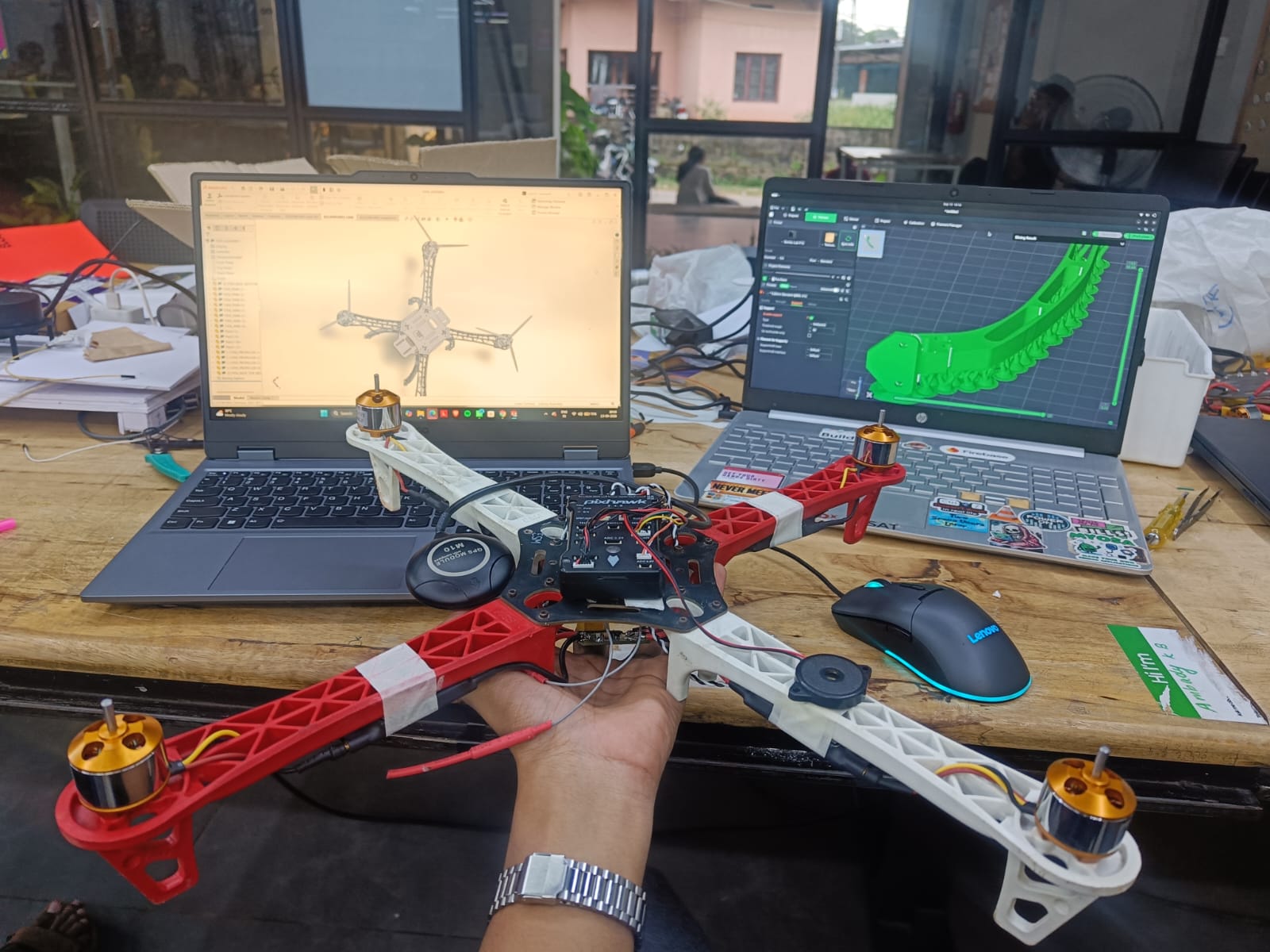
Week 9 — Pixhawk Calibration and First Flight
The final documented development stage focused on:
- Pixhawk configuration.
- PX4 firmware flashing.
- QGroundControl calibration.
- ESC connection correction.
- ArduPilot/Mission Planner experimentation.
- PX4 reflash and recalibration.
- First-flight preparation.
After resolving the documented configuration and connection issues, the drone completed its first flight.
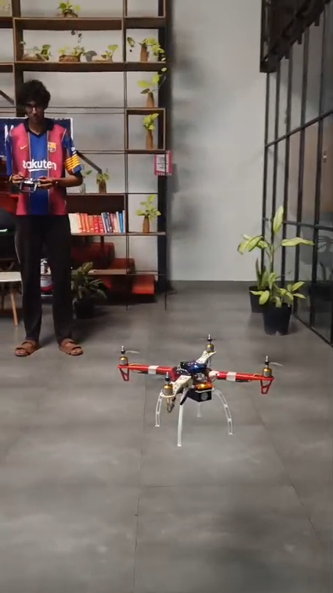
Repository Structure
InfiniteInferno/
│
├── README.md
├── LICENSE
│
├── code/
│   ├── configs/
│   │   └── config.yaml
│   │
│   ├── models/
│   │   ├── yolov8n.onnx
│   │   └── yolov8n.pt
│   │
│   ├── scripts/
│   │   └── pi_smoke_test.py
│   │
│   ├── src/
│   │   ├── __init__.py
│   │   ├── camera.py
│   │   ├── config.py
│   │   ├── controller.py
│   │   ├── detector.py
│   │   ├── gestures.py
│   │   ├── main.py
│   │   ├── postprocess.py
│   │   ├── preprocess.py
│   │   └── tracker.py
│   │
│   ├── tests/
│   │   ├── test_camera.py
│   │   ├── test_config.py
│   │   ├── test_detector.py
│   │   ├── test_model.py
│   │   └── test_tracker.py
│   │
│   ├── requirements.txt
│   └── pyproject.toml
│
└── docs/
    ├── week-00.md
    ├── Gesture_Drone_Week_1_ (2).md
    ├── Week_2_Model_Refinement_and_3D_Design.md
    ├── Week_3_Raspberry_Pi_Implementation_and_3D_Design_Testing.md
    ├── Week_4_Drone_Project_Log.md
    ├── Week_5_Drone_Project_Log.md
    ├── Week_6_Drone_Project_Log.md
    ├── Week_7_Drone_Project_Log.md
    ├── Week_8_Drone_Project_Log.md
    ├── Week_9_Drone_Project_Log.md
    │
    └── pics1/
        ├── WhatsApp Image 2026-09-17 at 11.48.52 PM.jpeg
        ├── WhatsApp Image 2026-09-17 at 11.51.14 PM.jpeg
        ├── WhatsApp Image 2026-09-17 at 11.52.14 PM.jpeg
        ├── WhatsApp Image 2026-09-17 at 11.53.48 PM.jpeg
        └── WhatsApp Image 2026-09-17 at 11.57.30 PM.jpeg
Requirements
The current Python project requires:
- Python
>= 3.11 - NumPy
>= 1.26, < 3 - ONNX Runtime
>= 1.19, < 2 - PyYAML
>= 6, < 7
On Raspberry Pi OS, the project expects the platform-provided packages for:
- Picamera2.
- OpenCV.
The repository's requirements.txt intentionally does not install those two platform packages through pip.
Installation
Clone the repository:
git clone https://github.com/BuilderinResidencyTinkerspace/InfiniteInferno.git
cd InfiniteInferno
Enter the Python project:
cd code
Create a virtual environment:
python3 -m venv .venv
Activate it:
source .venv/bin/activate
Install the Python dependencies:
python -m pip install --upgrade pip
python -m pip install -r requirements.txt
On Raspberry Pi OS, ensure the system packages for Picamera2 and OpenCV are installed through the operating system package manager.
Running the Vision Pipeline
From the code/ directory:
python -m src.main
The default configuration uses:
Camera backend: Picamera2
Resolution:      640 × 480
Model:           YOLOv8n ONNX
Inference stride: 2
OpenCV Camera
For an OpenCV camera:
python -m src.main --camera opencv --source 0
A video file can also be supplied as the OpenCV source:
python -m src.main --camera opencv --source path/to/video.mp4
Explicit Target Selection
A known track ID can be selected:
python -m src.main --target-id 1
The controller will only follow the selected session-local track.
Automatic First Target
For development/testing:
python -m src.main --auto-follow
The largest first visible confirmed person is selected.
Local Display
To show an annotated OpenCV preview:
python -m src.main --display
This requires a graphical OpenCV environment.
Limit the Number of Frames
For controlled testing:
python -m src.main --max-frames 100
Raspberry Pi Smoke Test
The repository includes:
code/scripts/pi_smoke_test.py
Run:
cd code
python scripts/pi_smoke_test.py
This performs a hardware-free model inference test and reports:
- CPU architecture.
- Operating system.
- Python version.
- Model input size.
- Model output shape.
- Overall status.
Example format:
{
  "machine": "aarch64",
  "os": "...",
  "python": "...",
  "model_input": [640, 640],
  "model_output": [1, 84, 8400],
  "status": "ok"
}
The exact output shape depends on the model file being used.
Testing
The project includes unit tests covering:
Camera
- Invalid backend handling.
- OpenCV stream failure behavior.
Detector
- Model input-shape handling.
- Injected inference session testing.
Preprocessing and postprocessing
- Letterbox geometry.
- Coordinate restoration.
- NMS.
- Pose-keypoint extraction.
Tracker
- ID persistence during motion.
- Brief occlusion handling.
- Multiple-person ID assignment.
Gestures
- Hold-frame debounce.
- Gesture cooldown.
- Both-hands priority.
Controller
- Target selection.
- Target loss behavior.
- Landing gesture handling.
- Protection against a bystander taking control.
Run the complete test suite:
cd code
python -m pytest
Example Output
The main application emits machine-readable JSON lines.
A representative intent looks like:
{
  "frame": 120,
  "fps": 18.7,
  "track_ids": [1, 2],
  "gestures": [],
  "intent": {
    "yaw": 0.12,
    "forward": 0.08,
    "vertical": -0.03,
    "action": "follow",
    "target_id": 1,
    "reason": "target locked"
  }
}
When following is disabled, the controller returns a safe default intent:
{
  "yaw": 0.0,
  "forward": 0.0,
  "vertical": 0.0,
  "action": "hover",
  "target_id": null,
  "reason": "follow mode disabled"
}
Project Images
Raspberry Pi Computer Vision
Initial person detection and tracking using the Raspberry Pi camera.
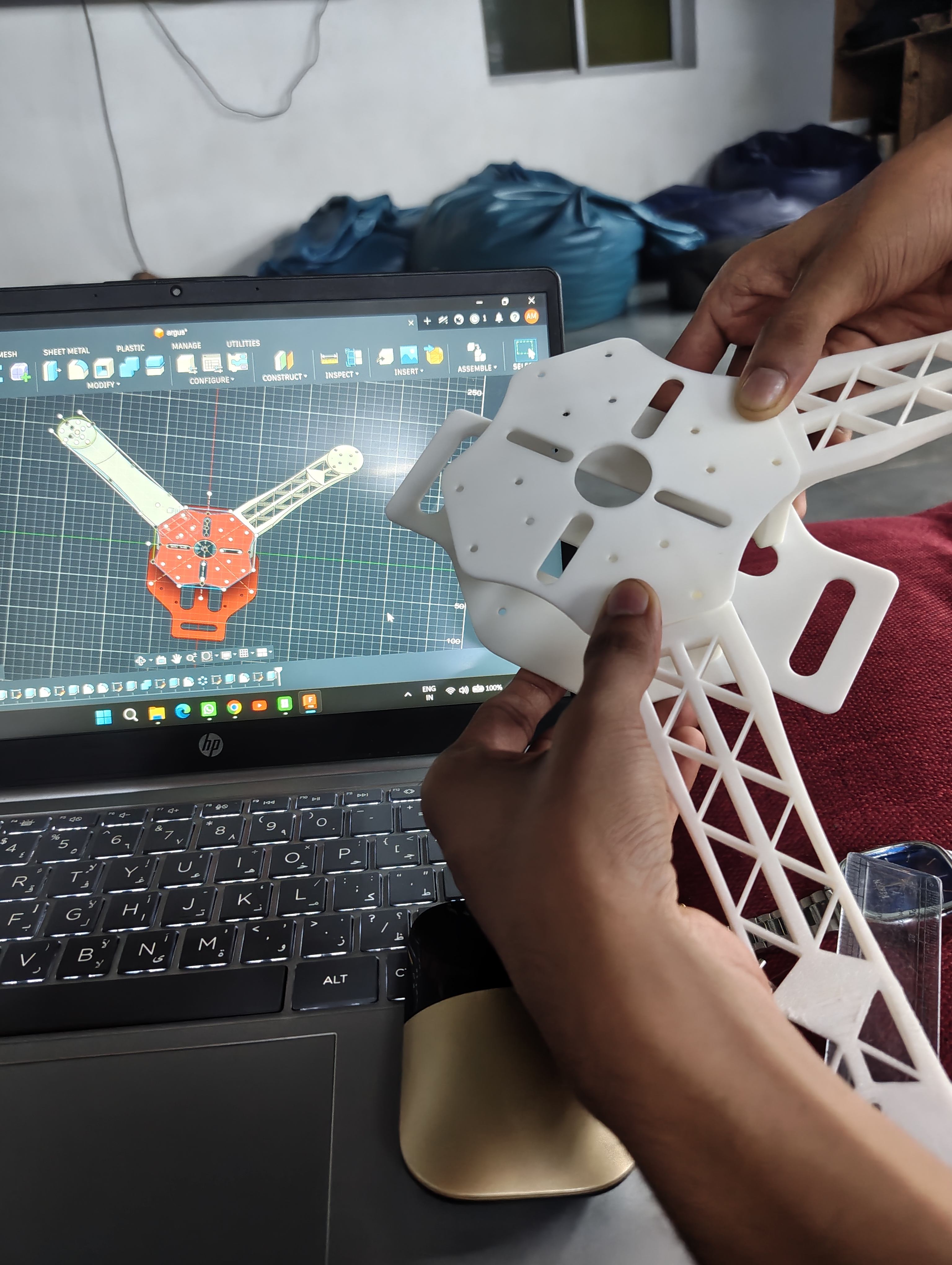
3D-Printed Drone Design
Physical development of the drone structure.
UNO Q Computer Vision
Documented computer-vision implementation on the Arduino UNO Q.
Hardware Assembly
Drone hardware assembly and component integration.
First Flight
Documented first-flight milestone.
Technical Design Notes
Edge Computing
The vision stack is designed for onboard/edge processing rather than requiring a remote server.
This reduces the dependency on network connectivity for the perception pipeline and allows the camera, detector, tracker, and control-intent generation to operate locally.
Lightweight Model
YOLOv8n was selected as a lightweight detection model suitable for experimentation on resource-constrained hardware.
The use of ONNX Runtime provides a deployment-oriented inference path.
Modular Tracking
Tracking is implemented separately from detection.
This means:
Detector
   ↓
Detections
   ↓
Tracker
   ↓
Persistent IDs
A detector update does not have to equal a new target identity.
Gesture Debouncing
Gestures require multiple consecutive frames before an event is emitted.
This reduces false triggers caused by:
- Keypoint noise.
- Temporary pose changes.
- Single-frame misdetections.
Bounded Control
The follow controller clamps movement values to configured limits.
This provides a defined interface for a future autopilot layer rather than allowing raw image geometry to directly generate unrestricted commands.
Limitations and Current Status
The repository should be understood as a development-stage autonomous-drone system, not as a complete production flight-control stack.
Current Python implementation
The checked-in vision software currently provides:
- Raspberry Pi camera support.
- OpenCV camera/video support.
- YOLOv8n ONNX inference.
- Person detection.
- Detection filtering and NMS.
- Lightweight person tracking.
- Track IDs.
- Pose-keypoint handling.
- Hand-gesture recognition.
- Target selection.
- Bounded follow intents.
- JSON output.
- Unit tests.
- Raspberry Pi model smoke testing.
Not currently implemented in this Python stack
The current repository code does not directly implement:
- Motor PWM control.
- ESC control.
- Direct MAVLink commands.
- Direct Pixhawk command transmission.
- Autonomous flight stabilization.
- Full obstacle avoidance.
- Production-grade visual-inertial navigation.
- GPS-based autonomous navigation.
Those functions belong to the flight-controller/autopilot integration layer and are separate from the current vision-intent prototype.
Project documentation vs. current code
The weekly documentation records the broader project evolution, including UNO Q implementation, physical drone assembly, Pixhawk calibration, and first flight.
The code/ directory is specifically the software vision/control prototype and should not be interpreted as containing the complete hardware or autopilot implementation.
Future Development
The modular architecture provides a path toward:
Current
  │
  ├── Person detection
  ├── Tracking
  ├── Gesture recognition
  └── Flight intent generation
          │
          ▼
Future integration
          │
          ├── MAVLink interface
          ├── Pixhawk command layer
          ├── Flight-state feedback
          ├── Target reacquisition
          ├── Obstacle avoidance
          ├── Better pose/gesture estimation
          ├── Hardware-accelerated inference
          └── Full autonomous mission logic
Potential optimization areas include:
- Model quantization.
- Hardware-accelerated inference.
- More efficient pose estimation.
- Better multi-object association.
- Improved target-reacquisition logic.
- Flight-controller feedback integration.
- Sensor fusion.
- Robust failsafe handling.
- Controlled outdoor flight testing.
Development Philosophy
ARGUS is structured around a separation of concerns:
PERCEPTION
Camera → Detection → Tracking

INTERPRETATION
Tracking + Pose → Gesture Events

DECISION
Target Geometry + Gesture Events → Flight Intent

AUTOPILOT
Flight Intent → Future MAVLink/Pixhawk Interface

ACTUATION
Autopilot → ESCs → Motors
Keeping these layers separate makes it easier to test the computer-vision system independently from the flight hardware and reduces the risk of coupling experimental vision code directly to motor control.
Documentation
The complete technical development history is available in the docs/ directory.
Weekly records:
Week 0 — IdeateWeek 1 — Computer Vision SetupWeek 2 — Model Refinement and 3D DesignWeek 3 — Raspberry Pi Implementation and 3D Design TestingWeek 4 — 3D Print Refinement and Drone PhysicsWeek 5 — Project BriefingWeek 6 — Frame Selection and UNO QWeek 7 — UNO Q Debugging and Computer VisionWeek 8 — Hardware Assembly and PDB ReplacementWeek 9 — Pixhawk Calibration and First Flight
License
This project is distributed under the license included in the repository.
See LICENSE for the complete license text.
04ResQmesh
A lightweight ESP32-based drone swarm for resilient emergency communication and environmental monitoring.
ResQmesh
A lightweight ESP32-based drone swarm for resilient emergency communication and environmental monitoring.
Project documentation
Weekly log Open repositoryResQmesh: Autonomous Ultra-Low-Cost ESP32 Swarm Drone Platform
<div align="center">





An ultra-affordable (<$25 / ₹2,224), open-source micro-quadcopter swarm platform powered by the ESP32-S3 ecosystem, engineered for distributed sensing, ad-hoc emergency mesh communication, and collaborative autonomous aerial coordination.
</div>Table of Contents
- The Story: Why ResQmesh Exists
- System Specifications & Architecture
- Complete Bill of Materials (BOM) & Budget
- Hardware Schematic & Wiring Blueprint
- Airframe 3D Printing & Fabrication Guide
- Firmware Architecture
- The Swarm Mesh Network: ESP-NOW + Phone SoftAP
- Step-by-Step Replication Guide (Zero to First Flight)
- Desktop Ground Control Station & Tools
- Repository Layout
- License & Acknowledgments
The Story: Why ResQmesh Exists
The Monolithic Problem
Modern commercial drone swarms and industrial UAVs are marvelous feats of engineering—and disastrously expensive. At $2,000 to $10,000 per unit, they rely on proprietary radio protocols, heavy STM32 architectures, complex RTK GPS beacons, and centralized ground command stations.
Worst of all, conventional aerial operations suffer from a single-point-of-failure: if one multi-thousand-dollar drone clips a branch, runs low on battery, or suffers radio jamming in a collapsed structure, the entire mission grinds to a halt.
Meanwhile, off-the-shelf toy micro-drones are cheap ($20–$30), but their hardware is locked down. They lack inter-agent communication, offer no access to raw flight dynamics, and cannot coordinate or share sensor telemetry.
The ₹3,000 Swarm Gamble
We asked a deceptively simple question:
Can we build an open-source, resilient, autonomous micro-drone swarm platform where each unit costs less than ₹2,500 ($25), weighs under 35 grams, and runs a deterministic 500 Hz hard-real-time flight loop alongside peer-to-peer mesh radio?
Ten weeks ago, this was just numbers scrawled across a workbench whiteboard. To hit this threshold, off-the-shelf flight stacks like Betaflight or ArduPilot were non-starters: they are built around dedicated RC receivers (ELRS/CRSF), expect STM32 hardware, and do not accommodate low-overhead, peer-to-peer swarm messaging on ESP32 silicon.
We had to write our own flight controller and mesh communication stack from scratch in C++.
The Workbench Battles
1. Snapped Arms & Slicer Shrinkage
Before you write a single line of flight code, your drone must obey Newton. Our early 5.0g skeletal 3D-printed frame flexed like a wet noodle when the motors spooled up. Under full thrust, the motor pods deflected by nearly 3°, causing the IMU to measure the bending of the plastic instead of the attitude of the aircraft.
When we shifted to a reinforced unibody design, our 7.00mm motor bores came off the 3D printer measuring 6.85mm due to thermal plastic shrinkage. Pressing a motor in by hand resulted in a sickening snap down the layer lines. The solution wasn't buying expensive carbon fiber; it was dialing in +0.12mm Horizontal Hole Expansion in the slicer, yielding a rigid 7.4g unibody with an exact 7.02mm friction fit.
2. The SOT-23 MOSFET Discovery
Most DIY drone projects try to drive standard power MOSFETs directly from 3.3V microcontroller pins, only to discover that the FETs never fully turn on. Standard gates require 4.5V to 10V to reach saturation. Driven with 3.3V, they act like high-resistance heaters, drop the battery voltage, and toast themselves.
Digging deep into datasheets, we uncovered the AO3400A N-Channel MOSFET in an ultra-compact SOT-23 package. With a gate threshold voltage ($V_{gs(\text{th})}$) between 0.65V and 1.45V, it is slammed completely into full saturation by the ESP32-S3's 3.3V logic. At $R_{ds(\text{on})} < 30\text{ m}\Omega$, it switches 2A of motor current with virtually zero thermal dissipation, eliminating the weight and cost of dedicated gate driver ICs.
3. Taming Motor EMI Noise
Brushed coreless motors at 50,000 RPM are miniature spark transmitters. Mechanical brush commutation produces violent micro-arcing, radiating electromagnetic noise straight into low-voltage sensor lines. Our first physical wiring run threw random I2C bus lockups on the MPU9250.
We cured this with three physical design rules:
- Tightly Twisted Motor Pairs: Twisting each motor's power leads (4 turns/cm) creates opposing magnetic fields that cancel radiated RF hash.
- 100nF Ceramic Tab Capacitors: Soldered directly across each motor's solder tabs to shunt RF arcing right at the spark source.
- Star Grounding: Routing high-current motor return paths directly to the battery negative pad, physically isolating them from the microcontroller's logic ground.
The Breakthrough: "It Fights Back!"
In Week 10, all subsystems converged. We held the 32.2g quadcopter loosely between two fingers, armed the flight controller, and bumped the throttle to 25%. The four 55mm props spun into a quiet, vibration-free blur at 20 kHz ultrasonic PWM.
When we pushed the nose down with a finger, the front two motors instantly surged with increased RPM while the rear two backed off, delivering a firm, gyroscopic counter-torque right into our fingertips. When we tilted it left, the left motors roared to restore level flight.
It felt alive. The hardware worked, the electrical efficiency exceeded 98%, the dual-core FreeRTOS architecture maintained a rock-solid 500 Hz flight loop, and the total build cost totaled ₹2,224 ($24.80).
System Specifications & Architecture
+-------------------------------------------------------------------------------+
|                      ResQmesh System Specifications                           |
+------------------------------+------------------------------------------------+
| Parameter                    | Value / Description                            |
+------------------------------+------------------------------------------------+
| Flight Controller MCU        | Seeed Studio XIAO ESP32-S3 (Dual-Core @ 240MHz)|
| Inertial Measurement Unit    | InvenSense MPU9250 / MPU6500 (400 kHz Fast I2C)|
| Flight Loop Execution Rate   | 500 Hz deterministic (2000 µs FreeRTOS cycle)  |
| Attitude Estimation          | Complementary Filter (α = 0.980, 500 Hz fusion)|
| Motor Drive PWM              | 20 kHz Ultrasonic LEDC (10-bit resolution)     |
| Low-Side Power Switches      | 4 × AO3400A Logic-Level N-Channel MOSFETs      |
| Propulsion System            | 4 × 720 Coreless Brushed DC + 55mm Propellers  |
| Power System                 | 1S 3.7V 380 mAh LiPo Battery (25C discharge)   |
| Inter-Drone Mesh Radio       | ESP-NOW 2.4 GHz Peer-to-Peer (sub-5ms latency) |
| Direct Mobile Link           | Autonomous Wi-Fi SoftAP + WebSockets (40 Hz)   |
| Failsafe Watchdog            | 200 ms signal-loss auto-disarm cutoff          |
| All-Up Flying Weight (AUW)   | 32.2 grams (including battery & airframe)      |
| Thrust-to-Weight Ratio       | 1.86 : 1 (Snappy attitude recovery)            |
| Total Build Cost per Node    | ₹2,224 (~$24.80 USD)                           |
+------------------------------+------------------------------------------------+
+-------------------------------------------------------------------------------+
|                     Dual-Core FreeRTOS Architecture                           |
+---------------------------------------+---------------------------------------+
|                CORE 0                 |                CORE 1                 |
|       (Wireless, Comms, & CLI)        |     (Deterministic Flight Physics)    |
+---------------------------------------+---------------------------------------+
| • Wi-Fi SoftAP HTTP & WebSocket Server| • 500 Hz Deterministic Timer (2000 µs)|
| • ESP-NOW Swarm Mesh Radio Rx & Tx    | • 14-Byte Contiguous I2C IMU Burst    |
| • CRC16 Packet Validation Engine      | • Complementary Attitude Filter       |
| • Swarm Peer Discovery & Table Sync   | • Cascaded Angle + Rate PID Loops     |
| • 200 ms Signal-Loss Watchdog         | • Dynamic Attitude Anti-Saturation    |
| • Interactive USB-C Serial Debug CLI  | • Quad-X Motor Torque Mixer           |
| • ADC Battery Moving-Average Filter   | • 20 kHz Hardware LEDC PWM Update     |
+---------------------------------------+---------------------------------------+
                    \                                       /
                     +--------> FreeRTOS Shared Memory <----+
Complete Bill of Materials (BOM) & Budget
Every part on this list is readily available from standard hobby robotics retailers, Amazon, or electronics distributors:
| Component | Qty | Spec / Footprint | Unit Cost (₹) | Total (₹) | Total ($ USD) | Function / Notes |
|---|---|---|---|---|---|---|
| Seeed XIAO ESP32-S3 | 1 | Dual LX7 240MHz, 2.4GHz RF | ₹850 | ₹850 | $9.50 | Flight controller MCU & mesh radio |
| MPU9250 IMU Breakout | 1 | 9-axis (Accel + Gyro) I2C | ₹420 | ₹420 | $4.70 | Fast attitude tracking at 400 kHz |
| 720 Coreless Brushed Motors | 4 | 7mm × 20mm (2x CW, 2x CCW) | ₹75 | ₹300 | $3.35 | 50,000 RPM high-thrust micro motors |
| 55mm Micro Propellers | 4 | 2x CW, 2x CCW (0.8mm bore) | ₹20 | ₹80 | $0.90 | High static thrust micro props |
| AO3400A N-Channel MOSFETs | 4 | SOT-23 ($V_{ds}=30\text{V}, R_{ds}<30\text{m}\Omega$) | ₹12 | ₹48 | $0.55 | 3.3V logic-level motor switches |
| 1N5819 Schottky Diodes | 4 | DO-41 / SOD-123 ($V_f \approx 0.45\text{V}$) | ₹4 | ₹16 | $0.18 | Inductive back-EMF flyback protection |
| Passives & Filter Caps | 1 set | 470µF 10V electrolytic + 100nF | ₹60 | ₹60 | $0.65 | Bulk decoupling & motor RF bypass |
| 1S 3.7V 380mAh LiPo | 1 | 25C discharge, JST-DS 1.25mm | ₹320 | ₹320 | $3.60 | ~4.5 minute hover flight time (~10.5g) |
| 3D-Printed Unibody Frame | 1 | PLA / PLA+ (7.4g) | ₹80 | ₹80 | $0.90 | Lightweight 3D printed unibody airframe |
| Wiring, JST & Perfboard | 1 set | 30 AWG silicone + 25×25mm perf | ₹50 | ₹50 | $0.55 | Power rail & motor harness |
| TOTAL PER FLIGHT NODE | — | — | — | ₹2,224 | $24.88 | Full working autonomous drone |
Hardware Schematic & Wiring Blueprint
                     +1S LiPo Positive Rail (3.0V - 4.2V)
                                   |
         +-------------------------+-------------------------+
         |                         |                         |
     +---+---+                 +---+---+                 +---+---+
     | 470uF | Bulk            | 10uF  | MCU             | 100kΩ | Voltage Divider
     | LowESR| Storage         | Cer   | Bypass          | (1%)  | High Side
     +---+---+                 +---+---+                 +---+---+
         |                         |                         |
        GND                       GND                        +-----> XIAO Pin D0 (ADC)
         |                         |                         |
         |                         |                     +---+---+
         |                         |                     | 100kΩ | Voltage Divider
         |                         |                     | (1%)  | Low Side
         |                         |                     +---+---+
         |                         |                         |
         |                         |                        GND
         |                         |
         |       +-----------------+-----------------+
         |       |                                   |
         |   +---+---+                           +---+---+
         |   | Motor | 720 Coreless              | Cathode 1N5819
         |   |  (+)  | Brushed Motor             |  [|]  | Schottky Diode
         |   |       |                           |  / \  | (Clamps flyback)
         |   | Motor | <====== [100nF Cap] =====>| Anode |
         |   |  (-)  |   (Shunts RF noise)       +---+---+
         |   +---+---+                               |
         |       |                                   |
         |       +-----------------+-----------------+
         |                         |
         |                         | Drain (Pin 3)
         |                    +----+----+
         |    ESP32-S3        |         | AO3400A N-Channel MOSFET
         |    PWM GPIO --[100Ω]-- Gate  | (SOT-23 Package)
         |                    | (Pin 1) | Vds=30V, Id=5.7A, Rds<30mΩ
         |                    |         |
         |                    +--[10kΩ]-+ Source (Pin 2)
         |                         |         |
         |                        GND        |
         |                                   |
         +-----------------------------------+
                           |
                   POWER STAR GROUND
             (Direct to LiPo Battery Negative)
Driver Circuit Design & MOSFET Selection
- AO3400A Logic-Level Gate Drive: Directly driven from 3.3V GPIO through a $100\ \Omega$ series damping resistor to suppress high-frequency LC gate ringing ($C_{iss} \approx 650\text{ pF}$).
- 10 kΩ Gate Pull-Down: Connected directly from Gate to GND. During microcontroller bootloader initialization or flashing, GPIO pins float in high-impedance mode. Without this resistor, gate capacitance charges randomly and spins the motors uncontrollably on power-up!
- 1N5819 Schottky Flyback Diodes: Brushed motors are inductive coils. When the MOSFET turns off, the collapsing magnetic field creates a voltage spike: $$V_{\text{spike}} = -L \frac{di}{dt}$$ Without the diode, this spike easily exceeds 40V, instantly punching through the MOSFET dielectric. The Schottky diode clamps the drain safely to $V_{bat} + 0.45\text{ V}$.
- 470 µF Bulk Low-ESR Capacitor: Placed directly across the battery rail adjacent to the MOSFET sources. When all four 720 motors punch out at full throttle, transient current steps exceed 7.5A. The bulk capacitor buffers these steps, preventing ESP32 brownout resets.
EMI Mitigation: Twisted Pairs & Star Grounding
- Twisted Motor Wiring: Motor leads are twisted together with $\ge 4\text{ turns/cm}$. Equal and opposite currents cancel radiated magnetic fields.
- 100nF Motor Tab Capacitors: Solder a 100nF 0805 or ceramic disc capacitor directly across each motor's terminal tabs to kill brush commutation noise before it reaches the wiring harness.
- Dedicated Power Star Ground: The high-current return wires from the four MOSFET sources and the 470µF capacitor meet at a single heavy-gauge copper node tied directly to the battery ground. Never route motor return currents through the delicate ground traces of the MPU9250 or XIAO board!
XIAO ESP32-S3 Pin Mapping
| Board Pin | ESP32-S3 GPIO | Subsystem / Function | Hardware Connection |
|---|---|---|---|
| D4 | GPIO5 | I2C SDA | Fast-Mode 400 kHz data to MPU9250 (4.7kΩ pull-up) |
| D5 | GPIO6 | I2C SCL | Fast-Mode 400 kHz clock to MPU9250 (4.7kΩ pull-up) |
| D2 | GPIO4 | Motor 1 (FL) | Front-Left (CW) -> 100Ω -> AO3400A Gate |
| D0 | GPIO1 | Motor 2 (FR) | Front-Right (CCW) -> 100Ω -> AO3400A Gate |
| D1 | GPIO2 | Motor 3 (RR) | Rear-Right (CW) -> 100Ω -> AO3400A Gate |
| D3 | GPIO3 | Motor 4 (RL) | Rear-Left (CCW) -> 100Ω -> AO3400A Gate |
| D8 | GPIO8 | Battery ADC | 2:1 divider (100kΩ / 100kΩ) sensing 1S LiPo |
| LED | GPIO21 | Status LED | Onboard active-LOW diagnostic indicator |
| 3V3 | — | 3.3V Regulated | Clean logic power to MPU9250 IMU |
| GND | — | Logic Ground | Tied to Power Star Ground at battery pad |
Airframe 3D Printing & Fabrication Guide
The unibody airframe is optimized for rapid FDM 3D printing on any entry-level printer (Ender 3, Bambu Lab, Prusa, etc.):
                  FRONT (Nose)
                       ^
                       |
         M1 (FL, CW)   |   M2 (FR, CCW)
            \          |          /
             \         |         /
              \   +----+----+   /
               \  | XIAO S3 |  /
      <--------+--| MPU9250 |--+--------> (Roll Right: +)
               /  +----+----+  \
              /        |        \
             /         |         \
         M4 (RL, CCW)  |   M3 (RR, CW)
                       |
                  REAR (Tail)
Slicer Configuration Profile
- Material: Standard PLA or PLA+ (e.g. eSUN PLA+).
- Layer Height:
0.16mmor0.20mm. - Perimeters / Wall Loops:
5(Ensure the motor arms are 100% solid plastic without hollow infill to eliminate vibration resonance). - Infill:
100%on arms,25% Gyroidon central electronics tray. - Critical Setting — Horizontal Hole Expansion: Set to
+0.12mm.
(This compensates for molten plastic shrinkage, guaranteeing the motor pods come off the bed at exactly 7.02mm for a snug, snap-free friction fit with 7.00mm motors). - Support: None required (designed with 45° self-supporting overhangs).
- Print Time: ~45 minutes.
Weight Budget Breakdown
| Subsystem Component | Target Weight | Actual Measured Weight |
|---|---|---|
| 3D Printed Unibody Frame (PLA) | 7.5 g | 7.4 g |
| 4 × 720 Coreless Brushed Motors | 18.0 g | 18.2 g |
| 4 × 55mm Propellers | 1.2 g | 1.1 g |
| Seeed Studio XIAO ESP32-S3 | 2.1 g | 2.1 g |
| MPU9250 IMU Breakout Board | 1.2 g | 1.2 g |
| MOSFET Driver Board + Passives | 2.0 g | 1.8 g |
| 1S 380mAh LiPo Battery | 10.5 g | 10.4 g |
| Wiring Harness & Solder | 1.5 g | 1.4 g |
| ALL-UP FLYING WEIGHT (AUW) | 44.0 g (Max) | 43.6 g (Flight Ready) |
Static thrust generated: 4 × 38g = 152g total thrust.
Thrust-to-weight ratio: $\frac{152\text{g}}{43.6\text{g}} = \mathbf{3.48 : 1}$ (plenty of power for sharp recovery).
Firmware Architecture
Dual-Core FreeRTOS Task Allocation
- Core 1 — Flight Loop Task (
Priority 24, Highest): Runs strictly every 2000 µs (500 Hz). Does not yield, does not perform dynamic memory allocations, and never blocks on Wi-Fi or serial operations. Executes IMU burst reads, attitude estimation, cascaded PID loops, dynamic anti-saturation mixer, and LEDC updates in under 420 µs, leaving $>75%$ deterministic CPU headroom. - Core 0 — Comms & Background Task (
Priority 5): Runs non-blocking Wi-Fi SoftAP HTTP/WebSocket services, handles ESP-NOW packet reception and heartbeat broadcasting, reads battery ADC moving averages, drives diagnostic LED blinks, and services the interactive USB Serial CLI.
Dynamic Priority Anti-Saturation Mixer
A classic pitfall in micro-quadcopters is motor saturation. When high throttle coincides with large roll, pitch, or yaw corrections, calculated motor outputs can exceed 1023 (100% duty). If outputs were simply clamped, differential torque is lost, causing the drone to flip and crash.
ResQmesh implements Dynamic Attitude Priority Anti-Saturation: $$M_1 (\text{FL}) = \text{Throttle} + \text{Roll} - \text{Pitch} - \text{Yaw}$$ $$M_2 (\text{FR}) = \text{Throttle} - \text{Roll} - \text{Pitch} + \text{Yaw}$$ $$M_3 (\text{RR}) = \text{Throttle} - \text{Roll} + \text{Pitch} - \text{Yaw}$$ $$M_4 (\text{RL}) = \text{Throttle} + \text{Roll} + \text{Pitch} + \text{Yaw}$$
If $\max(M_1, M_2, M_3, M_4) > 1023$: $$\text{Excess} = \max(M_1, M_2, M_3, M_4) - 1023$$ $$\text{Throttle} \leftarrow \text{Throttle} - \text{Excess}$$ All four motors are lowered equally. The drone sacrifices a few percent of climb rate while preserving 100% of its roll, pitch, and yaw stabilization torque!
Cascaded Dual-Loop PID Controller
- Outer Angle Loop (P-Loop): Converts stick tilt demands ($\pm30^\circ$) into desired angular rates ($\text{deg/s}$). $$\text{Target Rate} = K_{p,\text{angle}} \cdot (\text{Target Angle} - \text{Estimated Angle})$$
- Inner Rate Loop (PID-Loop): Compares desired angular rate with instantaneous gyro rates from the MPU9250. $$\text{Torque} = K_p \cdot e + K_i \int e , dt + K_d \frac{d(e_{\text{filtered}})}{dt}$$
- Derivative Low-Pass Filter: D-term is filtered through a 1st-order low-pass filter ($\tau = 0.005\text{ s}$, cutoff $\approx 31.8\text{ Hz}$) to eliminate high-frequency motor vibration buzz.
- Anti-Windup Clamping: Integrators are strictly bounded to prevent saturation overshoot during takeoff or ground strikes.
The Swarm Mesh Network: ESP-NOW + Phone SoftAP
ResQmesh solves the fundamental connectivity dilemma by running concurrent Dual-Mode Radio:
                  2.4 GHz Wi-Fi Hotspot (Channel 1)
 [Smartphone] <=====================================> [Drone #1 (Swarm Leader)]
 Touch UI       • 40 Hz Stick Control                 • SoftAP + WebSockets Server
 Browser        • Live HUD Telemetry                  • 500 Hz Real-Time Flight Loop
 (192.168.4.1)  • MESH: "2 NODES" (Peer Status)      • Swarm Peer Table
                                                               |
                                                               | Concurrent 2.4 GHz ESP-NOW
                                                               | Broadcasts (Channel 1)
                                                               v
                              +--------------------------------+-------------------------------+
                              |                                                                |
                              v                                                                v
                  [Drone #2 (Follower)]                                            [Drone #3 (Follower)]
                  • Pure ESP-NOW Mode 0                                            • Pure ESP-NOW Mode 0
                  • Executes Synchronized Sticks                                   • Executes Synchronized Sticks
                  • 10 Hz Heartbeat & Telemetry                                    • 10 Hz Heartbeat & Telemetry
Concurrent Dual-Mode Radio Operation
- The 2.4 GHz radio on the Seeed Studio XIAO ESP32-S3 is configured on Channel 1 for both Wi-Fi SoftAP and ESP-NOW (
WIFI_AP_CHANNEL == ESPNOW_WIFI_CHANNEL). - Drone #1 acts as the Swarm Leader / Bridge:
- It hosts the local Wi-Fi hotspot (
ResQmesh-Drone) and embedded HTTP/WebSocket server. - It concurrently initializes
esp_now_init()and registers the broadcast peer (FF:FF:FF:FF:FF:FF).
- It hosts the local Wi-Fi hotspot (
- As the pilot moves the virtual joysticks or slides the arm bar on their phone, Drone #1 applies the flight inputs locally and simultaneously re-broadcasts a
SwarmControlPacketwith CRC16 validation over ESP-NOW. - Follower drones listening on ESP-NOW receive the packet in $<5\text{ ms}$, executing the exact same maneuver in synchronized formation.
- All follower drones broadcast a 10 Hz
SwarmHeartbeatPacket. Drone #1 receives these, populates itsSwarmPeerTable, and reports"peers": Nover WebSocket, displayingMESH: 2 NODESdirectly on your phone screen!
Piloting with Any Smartphone (Zero-Install Touch UI)
No app store downloads, no drivers, no internet connection required:
- Turn on the drone. Connect phone Wi-Fi to
ResQmesh-Drone(Password:12345678). - Open Safari (iOS) or Chrome (Android) to
http://192.168.4.1. - Left Joystick: Throttle ($0-100%$) and Yaw (rudder, $\pm200^\circ/\text{s}$).
- Right Joystick: Pitch (nose forward/back) and Roll (bank left/right).
- Slide-to-Arm: Built-in safety interlock requires throttle at $0%$ to arm.
- Red KILL Button: Emergency cut zeroes all four motor duties in $<10\text{ ms}$.
- Trims & Max Throttle Limit: Set a 60% throttle ceiling for safe indoor flying.
Step-by-Step Replication Guide
Step 1: 3D Printing the Airframe
- Slice the unibody frame STL using the settings above:
- 5 wall perimeters (100% solid arms).
- Set Horizontal Hole Expansion to
+0.12mm.
- Print in PLA or PLA+.
- Clean any stringing from the central electronics bay.
- Test-fit one 720 coreless motor into a motor pod. It should insert with firm thumb pressure and stay securely locked without cracking the plastic.
Step 2: Soldering the MOSFET Driver Board
Cut a 25mm × 25mm section of standard 2.54mm perfboard:
- Mount the 4 × AO3400A MOSFETs: Use the dead-bug technique or orient them across adjacent pads.
- Solder the 10 kΩ Gate Pull-Down Resistors: Connect one between each MOSFET Gate (Pin 1) and Source (Pin 2).
- Solder the 100 Ω Gate Series Resistors: Connect one to each Gate pad, leaving the other leg free to receive the signal wire from the ESP32.
- Tie all 4 Sources together: Connect all Source pins (Pin 2) with solid copper bus wire. This forms the high-current Power Ground.
- Solder the 4 × 1N5819 Schottky Diodes: Connect each diode's Cathode (striped end) to the battery positive rail ($V_{bat}$) and Anode to the MOSFET Drain (Pin 3).
- Install the 470 µF Bulk Capacitor: Solder directly across the $V_{bat}$ and Power Ground rails on the board.
Step 3: Motors, Decoupling & Harness Assembly
- Press-fit the 4 × 720 coreless motors into the frame:
- Front-Left (M1): Clockwise (CW) motor (Red/Blue wires).
- Front-Right (M2): Counter-Clockwise (CCW) motor (Black/White wires).
- Rear-Right (M3): Clockwise (CW) motor (Red/Blue wires).
- Rear-Left (M4): Counter-Clockwise (CCW) motor (Black/White wires).
- Solder a 100nF ceramic capacitor directly across each motor's solder tabs.
- Tightly twist each motor's wire pair ($\ge 4\text{ turns/cm}$) and route them along the frame arms into the center tray.
- Connect each motor (+) to $V_{bat}$ and motor (-) to the respective MOSFET Drain.
- Solder the Seeed Studio XIAO ESP32-S3 and MPU9250 boards into the top deck:
- Connect XIAO 3.3V and GND to the MPU9250 power pins.
- Connect
GPIO5to MPU9250SDAandGPIO6toSCL. - Connect
GPIO4(M1),GPIO1(M2),GPIO2(M3),GPIO3(M4) to the respective 100Ω gate resistors.
Step 4: Toolchain Setup & Firmware Flashing
Option A: 1-Click Automated Flasher (Windows)
Plug your XIAO ESP32-S3 into your PC via USB-C and run:
.\code\ESP32-DRONE\flash_drone.bat
The script auto-detects your COM port, compiles the sketch with Arduino CLI, and flashes the firmware.
Option B: PlatformIO
cd code/ESP32-DRONE
pio run -t upload -t monitor
Option C: ESP-IDF
cd code/ESP32-DRONE
idf.py set-target esp32s3
idf.py build
idf.py -p COM_PORT flash monitor
Step 5: Automated Testing & Verification
Before connecting batteries, run the automated host unit tests on your PC:
cd code/ESP32-DRONE/tests
.\run_tests.bat
(Confirms all 73 algorithmic assertions pass: PID anti-windup, complementary filter convergence, anti-saturation mixer, CRC16 validation, battery alarms, and dual-mode mesh packet relay).
To run the full 500 Hz flight physics simulation:
.\run_simulation.bat
Step 6: Safe Commissioning Checklist (Props OFF!)
[!CAUTION] NEVER INSTALL PROPELLERS UNTIL ALL 12 STEPS BELOW ARE VERIFIED.
- Step 1: REMOVE ALL PROPELLERS.
- Step 2: Check Power Rails for Shorts. Use a multimeter in continuity mode across $V_{bat}$ and GND. Ensure resistance is $>1\text{ k}\Omega$ (no solder bridges).
- Step 3: Connect USB-C. Open serial monitor at 115200 baud. Confirm
statusprints healthy boot messages and IMU calibration succeeds. - Step 4: Verify Motor Spin Directions:
- In serial console, type
test_motor 1 5-> M1 (Front-Left) must spin Clockwise (CW). - Type
test_motor 2 5-> M2 (Front-Right) must spin Counter-Clockwise (CCW). - Type
test_motor 3 5-> M3 (Rear-Right) must spin Clockwise (CW). - Type
test_motor 4 5-> M4 (Rear-Left) must spin Counter-Clockwise (CCW).
- In serial console, type
- Step 5: Verify Attitude Estimation:
- Type
attitudein console. - Tilt drone 20° right wing down -> Roll must read $\approx +20.0^\circ$.
- Tilt drone 20° nose up -> Pitch must read $\approx +20.0^\circ$.
- Type
- Step 6: Verify Gyroscopic Counter-Torque:
- Arm the drone at 15% throttle.
- Physically tilt the drone right wing down with your fingers.
- The right motors (M2, M3) must automatically speed up and left motors (M1, M4) must slow down to resist the tilt.
- Step 7: Verify Failsafe Cutoff:
- With the drone armed, disconnect the Wi-Fi or close the browser controller.
- All 4 motors must instantly stop within 200 milliseconds.
Step 7: Tethered Hover & Initial Flight
- Install the 55mm propellers:
- Orange / Black CW Props on M1 (FL) and M3 (RR).
- Black CCW Props on M2 (FR) and M4 (RL).
- Attach a loose thread or elastic safety tether from the frame to a weighted object on the floor.
- Connect your phone to
ResQmesh-Drone, openhttp://192.168.4.1, and gently advance throttle past 35%. - Observe the aircraft enter a stable, level hover. Trim roll and pitch using the quick trim buttons on the mobile screen.
Desktop Ground Control Station & Tools
ResQmesh includes a high-performance desktop Ground Control Station (GCS) built with WebGL and HTML5:
- Launch Desktop GCS: Double-click open_gui.bat
- Real-time 3D attitude horizon and quadcopter wireframe visualizer.
- 4-channel real-time motor duty oscilloscopes.
- Live IMU accelerometer & gyroscope spectral FFT graphs.
- Tactical Swarm Radar displaying multi-node coordinates and peer health.
- Launch Mobile Preview: Double-click open_mobile_preview.bat
- Test and simulate the smartphone touch controller directly in your desktop browser.
Repository Layout
ResQmesh/
├── README.md                      # Complete project documentation & replication guide
├── mkdocs.yml                     # Documentation site generator config
├── docs/                          # Weekly engineering build logs (Week 1 to Week 10)
│   ├── index.md                   # Project overview and mission roadmap
│   ├── week-01.md                 # The ₹3,000 Swarm Gamble
│   ├── week-02.md                 # 3D Printing, Snapped Arms & Slicer Shrinkage
│   ├── week-03.md                 # Counting Pennies & Component Selection
│   ├── week-06.md                 # Hand-Wired Micro Flight Controller Blueprint
│   └── week-10.md                 # Dual-Core FreeRTOS Flight Loop & First Flight
├── code/
│   ├── README.md                  # Firmware and controller subsystem summary
│   ├── ESP32-DRONE/               # Primary Flight Controller & Swarm Firmware
│   │   ├── firmware/              # Arduino CLI sketch source & configurations
│   │   ├── main/                  # ESP-IDF / PlatformIO modular C++ source
│   │   │   ├── config.h           # Central pinout, timing & PID configuration
│   │   │   ├── flight_controller.cpp # 500 Hz deterministic FreeRTOS loop
│   │   │   ├── imu.cpp            # MPU9250 Fast-I2C driver & zero-bias calibration
│   │   │   ├── attitude.cpp       # 500 Hz complementary filter
│   │   │   ├── pid.cpp            # Cascaded outer angle + inner rate PID loops
│   │   │   ├── mixer.cpp          # Quad-X dynamic anti-saturation mixer
│   │   │   ├── motors.cpp         # 20 kHz LEDC ultrasonic PWM driver
│   │   │   ├── receiver.cpp       # Dual-mode Wi-Fi SoftAP + ESP-NOW Swarm Bridge
│   │   │   ├── swarm.h            # Multi-agent mesh framing & peer table
│   │   │   ├── web_ui.h           # PROGMEM-stored smartphone touch web app
│   │   │   └── cli.cpp            # Interactive USB-C serial debugging shell
│   │   ├── gui/                   # Desktop GCS & mobile web applications
│   │   │   ├── index.html         # 3D Attitude visualizer & Swarm Radar GCS
│   │   │   ├── mobile.html        # Smartphone touch flight controller web app
│   │   │   └── mobile_preview.html# Standalone browser simulator
│   │   ├── tests/                 # Automated native host test suite
│   │   │   ├── run_tests.bat      # 1-click test runner (73 unit test assertions)
│   │   │   └── run_simulation.bat # 500 Hz end-to-end flight physics simulator
│   │   └── flash_drone.bat        # 1-click automated USB-C flasher script
│   └── ESP32-CONTROLLER/          # Physical RC Transmitter / Ground Gateway
│       └── main/main.cpp          # ESP-NOW 50 Hz handheld transmitter firmware
└── cad/                           # 3D-printable airframe CAD models (STL, STEP)
License & Acknowledgments
This project is licensed under the MIT License — feel free to modify, replicate, and deploy for educational, research, or commercial swarm applications.
Developed as part of the Builder-in-Residence Program.
Lead Engineer: Jayasurya Jayakumar
05FIORA
Template repo for BIR projects. Click Use this template to start your own copy.
FIORA
Template repo for BIR projects. Click Use this template to start your own copy.
Project documentation
Weekly log Open repositoryBuilder-in-Residence — FIORA
Template repo for BIR projects. Click Use this template to start your own copy.
What goes where
docs/— project overview and weekly logs. This folder becomes your website.code/— firmware, scripts, anything runnable.cad/— 3D models and design files (STL, STEP, F3D, 3MF).
Preview the docs locally
pip install mkdocs-material
mkdocs serve
Open http://127.0.0.1:8000 and edit files under docs/ — the preview reloads as you save.
Publishing (GitHub Pages)
Every push to main rebuilds and publishes the site automatically (see .github/workflows/deploy.yml).
First-time setup:
- Push once and let the Action finish. It creates a
gh-pagesbranch. - Settings → Pages → Source: Deploy from a branch →
gh-pages/root.
Your site will be live at https://<org-or-user>.github.io/<repo>/.
Weekly logs
Fill in docs/week-01.md through docs/week-09.md as you go. Keep them short: what you did, what's blocking you, what's next.
06AquaNav
A bio-inspired autonomous rover that uses computer vision to detect and track fish movement, enabling the vehicle to navigate accordingly.
AquaNav
A bio-inspired autonomous rover that uses computer vision to detect and track fish movement, enabling the vehicle to navigate accordingly.
Project documentation
Weekly log Open repositoryBuilder-in-Residence — Project Template
Template repo for BIR projects. Click Use this template to start your own copy.
What goes where
docs/— project overview and weekly logs. This folder becomes your website.code/— firmware, scripts, anything runnable.cad/— 3D models and design files (STL, STEP, F3D, 3MF).
Preview the docs locally
pip install mkdocs-material
mkdocs serve
Open http://127.0.0.1:8000 and edit files under docs/ — the preview reloads as you save.
Publishing (GitHub Pages)
Every push to main rebuilds and publishes the site automatically (see .github/workflows/deploy.yml).
First-time setup:
- Push once and let the Action finish. It creates a
gh-pagesbranch. - Settings → Pages → Source: Deploy from a branch →
gh-pages/root.
Your site will be live at https://<org-or-user>.github.io/<repo>/.
Weekly logs
Fill in docs/week-01.md through docs/week-09.md as you go. Keep them short: what you did, what's blocking you, what's next.
07WATCH WING
WatchWing is a scratch-built, autonomous fixed-wing UAV . This document walks through the entire build - airframe, electronics, wiring, and software configuration — so it can be replicated from scratch.
WATCH WING
WatchWing is a scratch-built, autonomous fixed-wing UAV . This document walks through the entire build - airframe, electronics, wiring, and software configuration — so it can be replicated from scratch.
Project documentation
Weekly log Open repositoryWatchWing - Autonomous Fixed-Wing UAV
WatchWing is a scratch-built, autonomous fixed-wing UAV . This document walks through the entire build - airframe, electronics, wiring, and software configuration — so it can be replicated from scratch.
This is a first-time build, and this README includes the mistakes we made and what we'd do differently, not just the "correct" path. Read the Lessons Learned section before you start - it will save you real time.
1. Overview
- Airframe: Flite Test "Simple Scout" (stock plan, no custom scaling) - https://www.flitetest.com/articles/ft-simple-scout-build
- Flight controller: Pixhawk-class board (Pixhawk 2.4.8 / Pixhawk1) running ArduPilot's ArduPlane firmware
- Ground control: Mission Planner (Windows)
- Radio: FlySky FS-i6 transmitter + FS-iA10B receiver (PPM)
- Power: A2212 1400KV motor, SimonK 30A ESC, 3S LiPo battery
- Navigation: M10 GPS module with onboard compass (IST8310)
- Mission logic: GPS waypoint patrol, flight modes (Manual / FBWA / Loiter)
2. Full Parts List
| Component | Notes |
|---|---|
| Pixhawk-class flight controller | Pixhawk 2.4.8 or compatible, running ArduPlane |
| GPS + compass module (M10-based) | Two separate connectors: GPS over UART, compass over I2C |
| FS-i6 transmitter | Enable PPM output in transmitter menu |
| FS-iA10B receiver (or FS-iA6B) | Must support PPM output on a single wire |
| A2212 1400KV brushless motor | |
| SimonK 30A ESC | Signal wire connects to Pixhawk, not the battery |
| 3S LiPo battery (we used 3300mAh) | Connects directly to ESC, never to Pixhawk |
| Propeller | Sized to match motor/battery combo |
| SG90 servos ×4 | 2× aileron, 1× elevator, 1× rudder |
| Genuine Depron foam sheet, 5mm | Do not substitute — see Lessons Learned |
| Carbon rod or bamboo skewer | Wing spar |
| 3D printed parts | Motor mount/firewall, servo horns, linkage couplers |
| Hot glue gun | Foam assembly |
| Zip ties, tape | Securing the underbody hatch |
| USB cable, laptop | For flashing and Mission Planner |
3. Airframe — Build to the Flite Test Simple Scout Plan
We initially tried to custom-design our own wing dimensions. Not preferred The official Flite Test Simple Scout plan already matches a small electric motor class well: - https://www.flitetest.com/articles/ft-simple-scout-build
- Wingspan: 952mm
- Wing area: 20.9 dm²
- Target AUW: ~535.8g
- Wing loading: ~25.6 g/dm²
- CG: 62mm (2.44in) back from the wing's leading edge
Download the plan (full-size or tiled, depending on your printer) from Flite Test's site, print at verified 100% scale (check the calibration square before cutting anything), and trace it directly onto your foam.
Material — genuine Depron
We went through three materials before landing on the right one:
- PVC "Sunboard" — roughly 8x too dense. Do not use.
- Thermocol (EPS) sourced generically — too thick, and cutting it down to size with a hot-wire cutter (using a balsa template guide) went badly: the balsa scorched, the wire was slightly jagged and produced an uneven cut, and the wire itself eventually snapped.
- Genuine Depron, pre-cut to 5mm — this is what actually worked. It cuts cleanly with a sharp hobby knife, no hot-wire cutter needed.
If you're sourcing material yourself, ask specifically for Depron or RC/hobby-grade foam board by name, not generic "foam board" or "foam sheet" — those terms commonly return PVC signage board or packaging foam, neither of which is suitable.
Assembly
Follow the Flite Test build video/plan instructions for fold pattern, spar placement, and tail assembly.
4. Electronics Wiring
Power path
Battery (3S) ──► ESC power input (thick wires, direct connection)
ESC ──► Motor (thick wires)
ESC's BEC ──► Powers Pixhawk's servo rail (this is what powers the
              servos AND Pixhawk's own logic — battery never
              connects to Pixhawk directly)
Signal wiring — MAIN OUT channel assignments
| Pixhawk MAIN OUT | Connects to | Servo Function |
|---|---|---|
| 1 | Aileron servo (left) | Aileron |
| 2 | Elevator servo | Elevator |
| 3 | ESC signal wire | Throttle |
| 4 | Rudder servo | Rudder |
| 5 | Aileron servo (right) | Aileron2 |
Note: ArduPlane handles the opposite-direction movement between the two
aileron servos automatically once one is set to Aileron and the other to
Aileron2 — no manual reversing needed.
Receiver
FS-iA10B PPM output (single wire) ──► Pixhawk RC IN port
Enable PPM output in the transmitter's RX Setup menu before connecting.
GPS / Compass module
The module has two separate connectors:
- 4-pin connector (GPS, UART) → Pixhawk's GPS port
- I2C connector (compass) → Pixhawk's I2C/compass port
5. Software Setup (Mission Planner)
5.1 Flash ArduPlane
Setup → Install Firmware → Plane — select your board and let it flash.
Confirm "Upload Done" before continuing.
5.2 Accelerometer Calibration
Setup → Mandatory Hardware → Accel Calibration — rotate the board through
all six prompted positions (level, left, right, nose-up, nose-down, upside
down) and hold each steady for a few seconds.
5.3 Compass Calibration — important limitation
Setup → Mandatory Hardware → Compass — you can calibrate the internal
compass on the bench immediately. The external compass (on the GPS
module) needs to physically rotate through varied orientations together
with the Pixhawk as one rigid unit for the calibration to mean anything.
If they aren't mounted together yet, skip external compass calibration
until they are — you cannot do it properly with the two loose and separate.
5.4 Radio Calibration
Setup → Mandatory Hardware → Radio Calibration — move every stick and
switch through its full range, then save.
5.5 Servo Output — assign functions
Setup → Servo Output — assign each channel's function per the table in
Section 4. Confirm live "Position" values change as you move the sticks.
5.6 ESC Calibration — use the manual method
Mission Planner's one-click "Calibrate ESCs" button is built around
ArduCopter's parameter set and will fail on ArduPlane with a
"Please ensure your version is AC3.3+" error. Use the manual method
instead:
- Remove the propeller.
- Disconnect the battery.
- Move the throttle stick to full-up, hold it there.
- Connect the battery — the ESC beeps to confirm it registered max throttle.
- Move the throttle stick to full-down.
- The ESC beeps again, confirming the minimum.
- Disconnect and reconnect the battery normally.
5.7 Arming — the most common "nothing responds" cause
If your control surfaces move but the motor won't respond to throttle at all, this is very likely not a wiring or configuration problem — ArduPilot blocks all throttle output while disarmed, full stop. Check the Messages/pre-arm list for what's actually failing (commonly an incomplete compass calibration). Once pre-arm checks clear and the board is armed (via the rudder-arm gesture, or Mission Planner's Actions tab), throttle will respond immediately.
5.8 Custom AHRS Orientation (if mounting Pixhawk at an angle)
If your Pixhawk isn't mounted flat (ours was mounted on a side wall,
requiring Roll 90° + Yaw 180°), and the exact combination you need isn't in
the standard AHRS_ORIENTATION dropdown:
- Set
AHRS_ORIENTATIONto Custom1. - Set
CUST_ROT_ENABLE = 1. - Enter your actual mounting angles into
CUST_ROT1_ROLL,CUST_ROT1_PITCH,CUST_ROT1_YAW. - Write, reboot, and verify the artificial horizon responds correctly to the board's real physical attitude.
5.9 Flight Modes
Config → Flight Modes — assign a spare channel (we used Channel 5) as
your mode switch (FLTMODE_CH). We used a 3-position switch mapped as:
- Position 1: Manual
- Position 2: FBWA (fly-by-wire — holds a target bank/pitch angle, meaningfully more forgiving than Manual for a first-time pilot)
- Position 3: Loiter (circles a fixed GPS point)
6. Mounting Into the Airframe
- Mount servos into the wings/tail using 3D-printed servo horns; connect with bent-wire pushrods.
- Calculate CG before placing the battery; secure it with double-sided tape.
- Mount the Pixhawk (note its orientation — see Section 5.8 if not flat).
- Mount the receiver inside the body.
- Leave the GPS module exposed to the sky — it needs a clear view for satellite lock and cannot be enclosed like the other electronics.
- 3D-print and glue a firewall at the nose for the motor mount. (given in cad section)
- Close the underside hatch with tape and zip ties.
Once the Pixhawk and GPS are mounted together on the airframe, go back and complete the external compass calibration (Section 5.3) — this is the point where it finally becomes possible.
7. Before Your First Flight
- Practice on a simulator first. We used PicaSim (free). This is not optional — get real stick time before risking the airframe.
- Physically verify every control surface's direction against stick input before flying. A reversed elevator caused one of our crashes.
- Double-check your flight mode switch positions — know exactly which physical position corresponds to which mode, and rehearse switching between them without looking, before you're relying on it mid-flight.
- Remove the propeller for all bench/arming tests until you're actually ready to fly.
- Scout your flight location for obstacles (trees, power lines, buildings) before taking off.
8. Lessons Learned
- Material sourcing is the single biggest time sink in this build. Ask for Depron/EPP by name; verify density by weighing a sample before committing to a full sheet.
- "Servo works, motor doesn't" is almost always an arming/pre-arm issue, not a wiring problem. Check the Messages tab before assuming anything else is wrong.
- Mission Planner's automated ESC calibration doesn't work for ArduPlane — use the manual method from the start.
- External compass calibration requires the GPS and Pixhawk to be mounted together — don't attempt it while they're loose on a bench.
- FBWA is a better default flying mode than pure Manual for a first-time pilot — it limits how far the plane can bank/pitch, which meaningfully reduces stall risk during panicked, tight corrections.
- Flight mode switch mix-ups are a real, common failure mode — an accidental Loiter engagement mid-flight caused one of our crashes. Rehearse switch positions on the ground before trusting them in the air.
- A broken firewall in a crash is often a good outcome, not a bad one — so while 3d printing, give it low infill. it absorbed impact energy that would otherwise have gone into the motor or fuselage.
9. Status
WatchWing achieved three powered manual test flights.. The airframe was damaged beyond repair on the third crash.
08OpenMove
An open-source automatic chessboard. Because moving pieces manually is overrated
OpenMove
An open-source automatic chessboard. Because moving pieces manually is overrated
Project documentation
Weekly log Open repositoryOpenMove
OpenMove is my attempt to build an automatic chessboard that can move pieces from underneath the board. The idea is straightforward. The implementation is not. Magnets, belts, loose tolerances, and chess pieces have opinions.
Right now this is an experimental XY-motion prototype, not an autonomous chessboard. The current job is proving that the carriage can move repeatably between squares. Everything above that layer—pickup, sensing, engine play, and a complete game—waits its turn.
What exists today
| Part | Current direction | Reality check |
|---|---|---|
| Controller | Arduino Uno + CNC Shield V3 | Firmware 2.7 / protocol 7 uploaded |
| Motion | 2 × NEMA 17, 2 × DRV8825, GT2 belts | Experimental; full travel unvalidated |
| Linear support | 2 × 4 mm × 300 mm rods | Experimental |
| Pickup | MG90S servo + permanent magnet | Mechanism exists; piece pickup unvalidated |
| Mapping | a1 origin, X a→h, Y 1→8, 44 mm pitch | Jog directions confirmed; accuracy unmeasured |
| Desktop control | PySide6 GUI and terminal UI | Experimental, with firmware trust checks |
| Chess replay | Non-capture standard-start PGNs only | Software path only; no physical replay yet |
| Sensing | 8 × 8 Hall grid is the idea | Not built or validated |
| Engine | Containerized Stockfish API | Separate from the physical board |
The board will not reliably play a game yet. Captures, castling, en passant, promotion, automatic homing, full-square repeatability, and collision clearance are all unfinished. Calling it “AI chessboard complete” now would be LinkedIn fiction with stepper motors.
The split that keeps this project sane
physical board ──> host controller ──> chess engine
      ^                   |
      |                   v
XY carriage <──── Arduino low-level motion
The Arduino handles pins, steps, timing, and the magnet actuator. The host is responsible for chess rules, game state, UI, and any future online work. Engine output never gets to move hardware by itself; the host must confirm it still matches the board state first.
Hardware direction
- Arduino Uno and CNC Shield V3
- Two NEMA 17 motors and two DRV8825 drivers
- GT2 belt drive and two 4 mm × 300 mm stainless-steel rods
- 12 V motion-power target
- MG90S servo driving a 3D-printed permanent-magnet mechanism
These are prototype decisions, not a shopping list carved into stone. The rod choice, XY kinematics, pickup design, sensing architecture, host language, and serial protocol can change when tests give a good reason.
Running the experimental tools
Firmware
The sketch is code/openmove_chess/openmove_chess.ino.
Compile/upload it for an Arduino Uno with the Arduino IDE or Arduino CLI.
arduino-cli compile --fqbn arduino:avr:uno code/openmove_chess
arduino-cli upload --port /dev/ttyUSB0 --fqbn arduino:avr:uno code/openmove_chess
An upload clears manual home and board confirmation. Set the carriage at the
real a1 centre, then home and reset/confirm the board before requesting any
movement. Start with small jogs; do not jump straight to a PGN because you are
feeling brave.
Desktop GUI
python -m venv .venv
source .venv/bin/activate
pip install -r code/requirements-gui.txt
python code/openmove_gui.py --port /dev/ttyUSB0
The GUI is deliberately strict about the controller mapping and trust state. If home or board confirmation is lost, stop, re-home, and reset the board. A failed move or replay does not put physical pieces back for you.
For the lower-level coordinated motor/servo test, read
code/hardware_smoke_test/README.md
before uploading it. In particular: the servo needs suitable regulated 5 V
power with common ground, never the 12 V motor supply.
Project map
docs/— the build journal, Weeks 0–9code/— firmware, GUI, terminal UI, and smoke testcad/— mechanical files and reference assetsstockfiash/— the deliberately separate Stockfish API
Next useful test
Validate repeatable full-square XY travel from a1, then add homing and test
the magnet moving exactly one piece. That is the next honest milestone. More
chess logic before that is just avoiding the hard mechanical work with extra
syntax.
09MOMO AI Alzheimers Companion
An AI-powered tabletop companion designed to support Alzheimer's patients through voice interaction, reminders, memory assessment, cognitive activities, activity monitoring, and caregiver support.
MOMO AI Alzheimers Companion
An AI-powered tabletop companion designed to support Alzheimer's patients through voice interaction, reminders, memory assessment, cognitive activities, activity monitoring, and caregiver support.
Project documentation
Weekly log Open repositoryMOMO-AI-Alzheimers-Companion
An AI-powered tabletop companion designed to support Alzheimer's patients through voice interaction, reminders, memory assessment, cognitive activities, activity monitoring, and caregiver support.
10AURABot
AURABot (Aquatic Unit for Revival & Algae-Management) — an ESP32-controlled twin-hull robot that clears surface litter and combs submerged algae to restore a stagnant municipal pond in Kochi, without disturbing bottom sediment. Remote-controlled, open-source, proof-of-concept for scalable urban water restoration.
AURABot
AURABot (Aquatic Unit for Revival & Algae-Management) — an ESP32-controlled twin-hull robot that clears surface litter and combs submerged algae to restore a stagnant municipal pond in Kochi, without disturbing bottom sediment. Remote-controlled, open-source, proof-of-concept for scalable urban water restoration.
Project documentation
Weekly log Open repositoryAURABot (Aquatic Unit for Revival & Algae-management)
Section 07 — Partners
Partners and organisers.
Partnered with

Organised by